
Fluorescence quantitative detector

A fluorescence quantitative and detector technology, applied in the field of medical testing, can solve the problems of insufficient objectivity, large size, and inconvenience for instant testing.

Inactive Publication Date: 2012-04-25
GUANGZHOU WONDFO BIOTECH
View PDF4 Cites 8 Cited by
  • Summary
  • Abstract
  • Description
  • Claims
  • Application Information

AI Technical Summary

Problems solved by technology

The main disadvantages are: the problem of non-specific staining has not been completely resolved, the objectivity of the result judgment is insufficient, and the technical procedures are still relatively complicated
However, the general-purpose fluorescent quantitative detectors in the prior art are usually large in size, which is not convenient for instant inspection, which limits its development in inconvenient transportation and underdeveloped areas.

Method used


Image

  • Fluorescence quantitative detector
  • Fluorescence quantitative detector
  • Fluorescence quantitative detector

Examples


Embodiment Construction

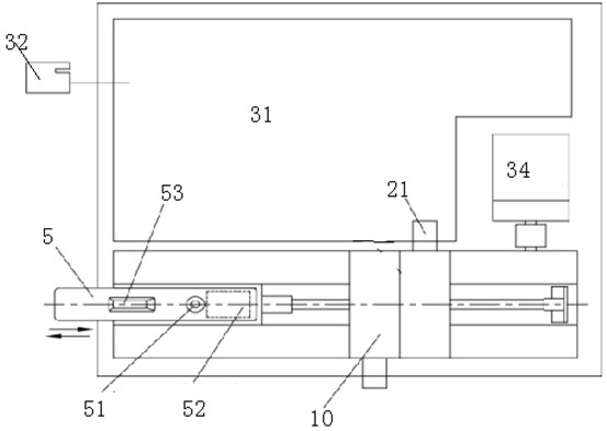
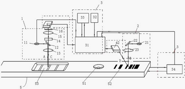
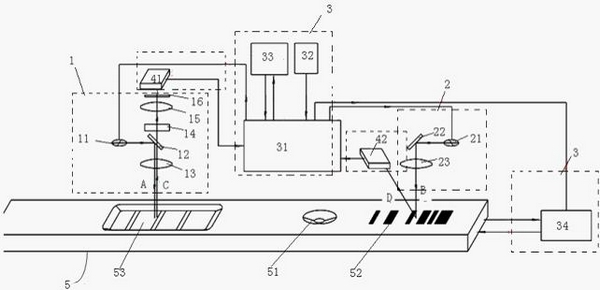
[0035] The following combination figure 1 and figure 2 The present invention will be described in detail with specific examples.

[0036] The fluorescence quantitative detector of the present invention includes an excitation light source module 10, a photoelectric conversion module, and a control analysis module 3. The excitation light source module includes a first laser module assembly 1 and a second laser module assembly 2. The photoelectric conversion module includes a first A photoelectric conversion module 41 and a second photoelectric conversion module 42; the first laser module assembly 1 is used to emit the excitation beam A into the detection area 53 of the reagent strip; the second laser module assembly 2 is used to emit the excitation beam A to the coding area on the reagent strip Exciting beam B; the photoelectric conversion modules 41 and 42 are used to receive reflected fluorescent signal C and laser signal D and perform photoelectric signal conversion; the co...


PUM

PropertyMeasurementUnit
Wavelengthaaaaaaaaaa

Abstract

The invention relates to a fluorescence quantitative detector which comprises an excitation light source module, a photoelectric conversion module, a control analysis module, and a software module; the excitation light source module comprises a first laser module assembly and a second laser module assembly; the first laser module assembly is used for emitting an excitation light beam A to a detection zone of a reagent strip; the second laser module assembly is used for emitting an excitation light beam B to a coding zone of a reagent strip; the photoelectric conversion module is used for receiving a reflected fluorescence signal C and a laser signal D, and performing photoelectric signal conversion; the control analysis module comprises a main circuit, a motor, and a display screen, and the control analysis module is used for treating and receiving electric signals outputted by the photoelectric conversion module; the fluorescence quantitative detector is provided with a reagent strip slot and an ID card slot which are used for accommodating the reagent strip and a calibration chip ID card; the motor is used for driving the reagent strip to move. the fluorescence quantitative detector of the invention adopts a specially-designed optical system and compensating circuit, and makes immunofluorescence quantitative detection become more sensitive and accurate.

Description

[0001] 【Technical field】 [0002] The invention belongs to the field of medical inspection, in particular to a fluorescence quantitative detector for capturing fluorescence signals. [0003] 【Background technique】 [0004] Immunofluorescence detection technology has been successful since Coons et al. first used fluorescein for labeling in 1941. This technique of labeling antibodies with fluorescent substances for antigen localization is called fluorescent antibody technique (fluorescent antibody technique). The method of using fluorescent antibody to trace or check the corresponding antigen is called fluorescent antibody method; the method of using known fluorescent antigen markers to trace or check the corresponding antibody is called fluorescent antigen method. These two methods are collectively called immunofluorescence technology, because fluorescent pigments can not only be combined with antibody globulins to detect or localize various antigens, but also can be combin...

Claims


Application Information

Patent Timeline
IPC IPC(8): G01N21/64G01N33/558
Inventor 王继华王治才
Owner GUANGZHOU WONDFO BIOTECH
Learn More