Switch gear of small-sized electronic product

A technology for electronic products and switching devices, applied in the field of power switches, can solve the problems of increasing manufacturing costs, increasing manufacturing costs, increasing product assembly time, etc., and achieving the effects of reducing the number of uses, reducing manufacturing costs, and reducing manufacturing processes.

Inactive Publication Date: 2012-04-25
梁清晖
View PDF6 Cites 4 Cited by
  • Summary
  • Abstract
  • Description
  • Claims
  • Application Information

AI Technical Summary

Problems solved by technology

[0003] The above method, such as setting a mechanical switch on the line connected to the positive pole of the battery, will increase the manufacturing cost on the one hand, and increase the time of product assembly on the other hand; if designing the switch circuit on the circuit board, it will also increase the manufacturing cost. After the electronic product is turned off, the battery is still connected to some circuits, and the battery will be discharged slowly. When the electronic product is not used for a long time, the power of the battery will be wasted and the life of the battery will be affected

Method used


Image

  • Switch gear of small-sized electronic product
  • Switch gear of small-sized electronic product
  • Switch gear of small-sized electronic product

Examples


Embodiment 1

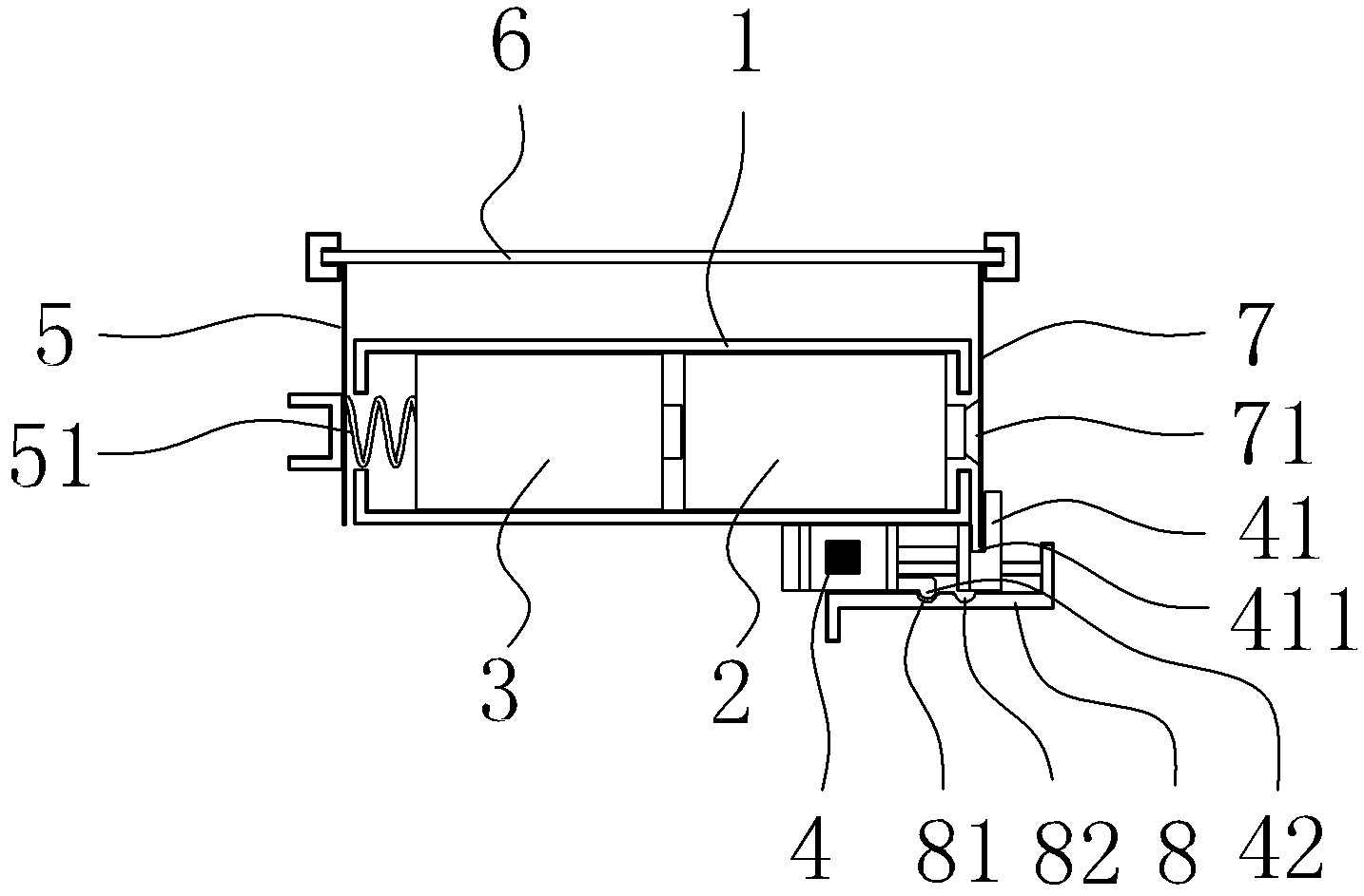
[0021] Embodiment one: figure 1 As shown, a switch device for a small electronic product includes a battery box 1, two batteries 2, 3 and a toggle button 4. The two batteries 2, 3 are connected in series and installed in the battery box 1, close to the negative pole of the battery 3. The side is provided with a fixed conductive sheet 5 and an elastic element 51, the fixed conductive sheet 5 is connected to the negative pole of the battery 3 through the elastic element 51, and the fixed conductive sheet 5 is connected to the negative electrode on the circuit board 6 for the negative output terminal of the power supply. 1 There is a gap on the side close to the positive pole of the battery 2, and a movable conductive sheet 7 is arranged outside the battery box 1. One end of the movable conductive sheet 7 is a fixed end and is connected to the positive electrode of the circuit board 6 as the positive output end of the power supply. The movable conductive sheet The other end of 7 ...

Embodiment 2

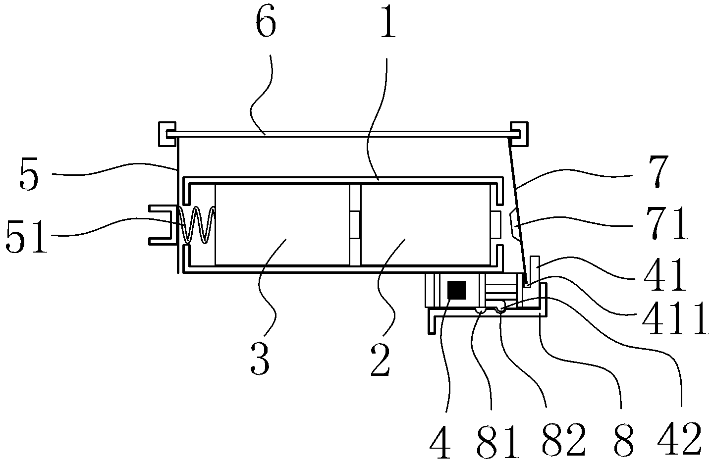
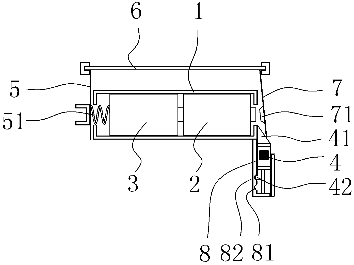
[0025] Embodiment two: image 3 As shown, it is different from Embodiment 1 in that the front part 41 of the toggle button 4 is wedge-shaped, the track 8 is perpendicular to the axes of the batteries 2 and 3, and the raised contact 71 of the movable conductive sheet 7 passes through the battery case 1. The gap and the positive pole of the battery 2 are kept in a normally closed state. When the front part 41 of the toggle button 4 is inserted forward, the movable conductive sheet 7 is moved to disengage the protruding contact 71 of the movable conductive sheet 7 from the positive electrode of the battery 2, and at the same time, the The positioning protrusion 42 on the side wall of the button 4 matches with the positioning groove 82 on the side of the track 8 .

[0026] Figure 4 Shown is the top view of the second embodiment of the present invention when the power is turned on. The toggle button 4 is retracted, and the raised contact 71 of the movable conductive sheet 7 is en...


PUM


Abstract

The invention discloses a switch gear of a small-sized electronic product. The switch gear comprises a battery box, a battery and a toggle button, wherein the battery is arranged in the battery box; a fixed conductive sheet and an elastic element are arranged at one side which is close to a battery cathode; the fixed conductive sheet is connected with the battery cathode through the elastic element and the fixed conductive sheet is an output end of a power supply cathode; a notch is arranged at one side of the battery box, which is close to a battery anode; a movable conductive sheet is arranged outside the battery box and one end of the movable conductive sheet is a fixed end and is used as an output end of a power supply anode; the other end of the movable conductive sheet is a movable end and is provided with a convex contact; the front part of the toggle button is provided with a clamping groove or is wedge-shaped; by toggling the movable conductive sheet by the toggle button, the convex contact on the movable conductive sheet is connected or disconnected with the battery anode through the notch on the battery box. The switch gear of the small-sized electronic product, provided by the invention, has the advantages of saving a power supply switch of the electronic product, reducing use quantity of elements, reducing manufacturing flows, reducing manufacturing cost, and assuring that the battery is not consumed when the electronic product is not used.

Description

technical field [0001] The invention relates to the technical field of a power switch, in particular to a switch device which uses a battery to provide power to small electronic products and can conveniently control the power on and off of the battery. Background technique [0002] At present, most of the small movable electronic products such as toys and low-power LED lights are powered by batteries. The batteries are installed in the battery box. The power consumption part of the product is connected. Under normal circumstances, the electronic product must also be equipped with a switch to control the on and off of the power supply, so that the electronic product can be in use or not in use; the usual practice is to connect the positive pole of the battery Set a mechanical switch on the circuit, or design a switch circuit on the circuit board of the electronic product, and cooperate with the electronic switch or mechanical switch to complete the opening and closing of the ...

Claims


Application Information

Patent Timeline
Patent Type & Authority Applications(China)
IPC IPC(8): H01H15/02H01M2/10
CPCY02E60/12Y02E60/10
Inventor 梁清晖
Owner 梁清晖
Why Eureka
Try Eureka