Heat-fusing body

A thermal fuse, metal shell technology, applied in the direction of heating/cooling contact switches, etc., can solve the problems of large amount of epoxy resin, affecting the appearance of the product, and the epoxy resin seal is prone to collapse, so as to reduce the amount of epoxy resin, The effect of improving electrical insulation

Inactive Publication Date: 2012-04-25
JIANGYIN ZHIXIANG ELECTRONICS TECH
View PDF5 Cites 3 Cited by
  • Summary
  • Abstract
  • Description
  • Claims
  • Application Information

AI Technical Summary

Problems solved by technology

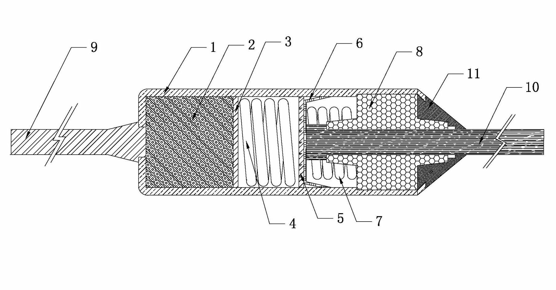
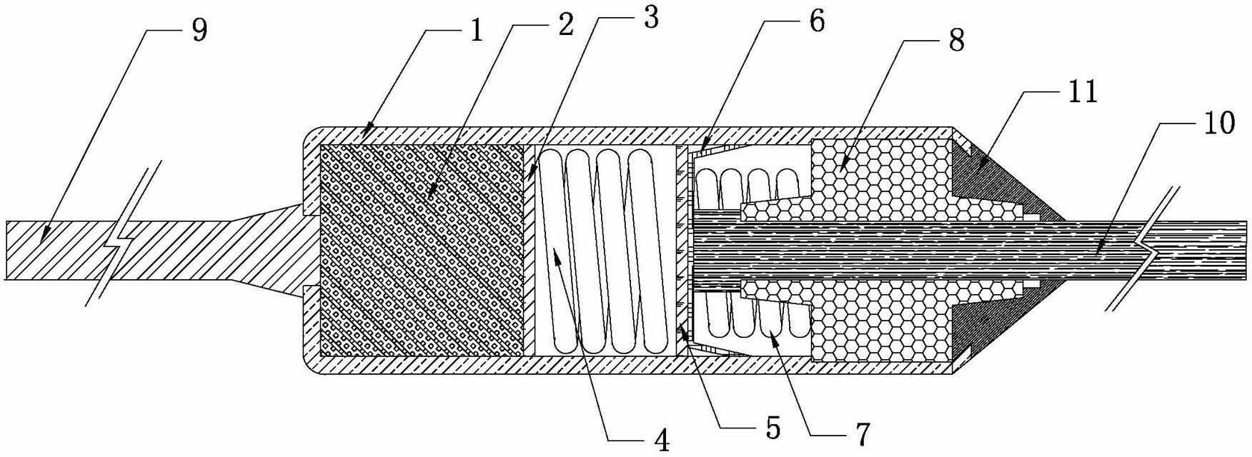
[0002] Thermal fuses are also called thermal fuses, which include metal shells, temperature-sensitive particles, front gaskets, rear gaskets, drum springs, breaking electrodes, breaking springs, ceramic beads, riveting wires and contact wires. The riveting wires are riveted on One end of the metal shell, and then temperature-sensitive particles, gaskets, drum springs, rear gaskets, breaking electrodes, breaking springs and ceramic beads are tightly installed on the metal shell in turn, and the contact wires are connected to the ceramic beads. The me

Method used


Image

  • Heat-fusing body
  • Heat-fusing body
  • Heat-fusing body

Examples


Embodiment Construction

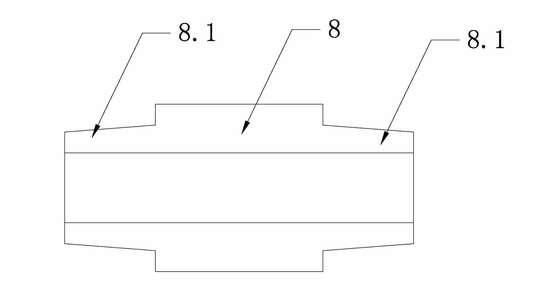
[0008] Such as figure 1 and figure 2 A thermal fuse is shown, including a metal shell 1, temperature-sensitive particles 2, front gasket 3, drum spring 4, rear gasket 5, breaking electrode 6, breaking spring 7, ceramic beads 8, riveting wire 9 and contacts Dot line 10; the port of the metal shell 1 at the junction of the contact line 10 and the ceramic bead 8 is sealed with epoxy resin 11; the characteristic is that there is a protruding head 8.1 at both ends of the ceramic bead 8.


PUM


Abstract

The invention relates to a heat-fusing body, comprising a metal shell, temperature-sensitive particles, a front gasket, a rear gasket, drum-shaped springs, a breaking electrode, breaking springs, porcelain beads, a riveting line and a contact line, wherein a port of the metal shell at the connecting position of the contact line and the porcelain beads is sealed by epoxy resin. The heat-fusing body is characterized in that the two ends of each porcelain bead are respectively provided with a convex head. The heat-fusing body has the advantages that the electric insulativity of a finished product can be improved, the used amount of epoxy resin is reduced and the collapse does not easily occur because the port is sealed by the epoxy resin.

Description

technical field [0001] The invention relates to a thermal fuse, in particular to a thermal fuse using temperature-sensitive particles as a heat sensitive body. Background technique [0002] Thermal fuses are also called thermal fuses, which include metal shells, temperature-sensitive particles, front gaskets, rear gaskets, drum springs, breaking electrodes, breaking springs, ceramic beads, riveting wires and contact wires. The riveting wires are riveted on One end of the metal shell, and then temperature-sensitive particles, gaskets, drum springs, rear gaskets, breaking electrodes, breaking springs and ceramic beads are tightly installed on the metal shell in turn, and the contact wires are connected to the ceramic beads. The metal shell port at the connection is sealed with epoxy resin, because the current ceramic bead has a protruding head at one end, and the other end is flat; because the shape of the epoxy resin seal is conical, and the ceramic bead is flat when insta...

Claims


Application Information

Patent Timeline
IPC IPC(8): H01H37/76
Inventor 马志军
Owner JIANGYIN ZHIXIANG ELECTRONICS TECH
Why Eureka
Try Eureka