Internal steel tube confined reinforced concrete hollow pier

A technology of reinforced concrete and inner steel pipes, which is applied in the field of bridge pier structures, can solve problems such as changes in the mechanical properties of concrete outside, difficulty in erecting and dismantling internal formwork, and internal support of difficult external concrete, so as to eliminate erection and demolition procedures and avoid adverse effects , the effect of improving bearing capacity and ductility

Inactive Publication Date: 2012-05-02
NANJING FORESTRY UNIV
View PDF5 Cites 15 Cited by
  • Summary
  • Abstract
  • Description
  • Claims
  • Application Information

AI Technical Summary

Problems solved by technology

[0004] Common reinforced concrete hollow piers have the following problems in application: 1) Due to the hollowness inside the cross-section, the concrete on the side wall of the pier loses internal constraints, and is in an internal unconstrained state, with poor mechanical properties; 2) There is no support on the inner side of the concrete on the side wall of the pier, It is easy to be damaged under ship impact and earthquake load, and it is prone to damage of concrete indentation; 3) The side wall concrete of the hollow section of the pier is prone to local buckling damage under load, and its wall thickness is severely limited by the diameter-thickness ratio; 4) The internal space of the hollow pier is narrow, and it is extremely difficult to erect and dismantle the internal formwork during construction
[0005] Simply pour steel pipes into reinforced concrete hollow piers to form ordinary hollow steel pipe-reinforced concrete composite components, such as Chinese patent 200920220225.2, its bearing capacity is only a simple superposition of internal steel pipes and external reinforced concrete Provide effective internal support, but cannot bring about essential changes in the mechanical properties of external concrete, and cannot provide effective protection for concrete concave damage

Method used


Image

  • Internal steel tube confined reinforced concrete hollow pier
  • Internal steel tube confined reinforced concrete hollow pier
  • Internal steel tube confined reinforced concrete hollow pier

Examples


Embodiment

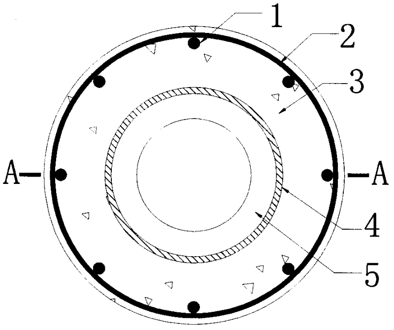
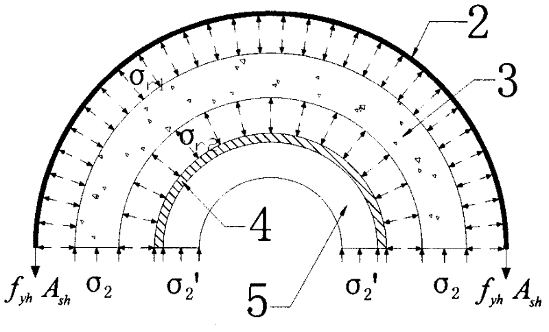
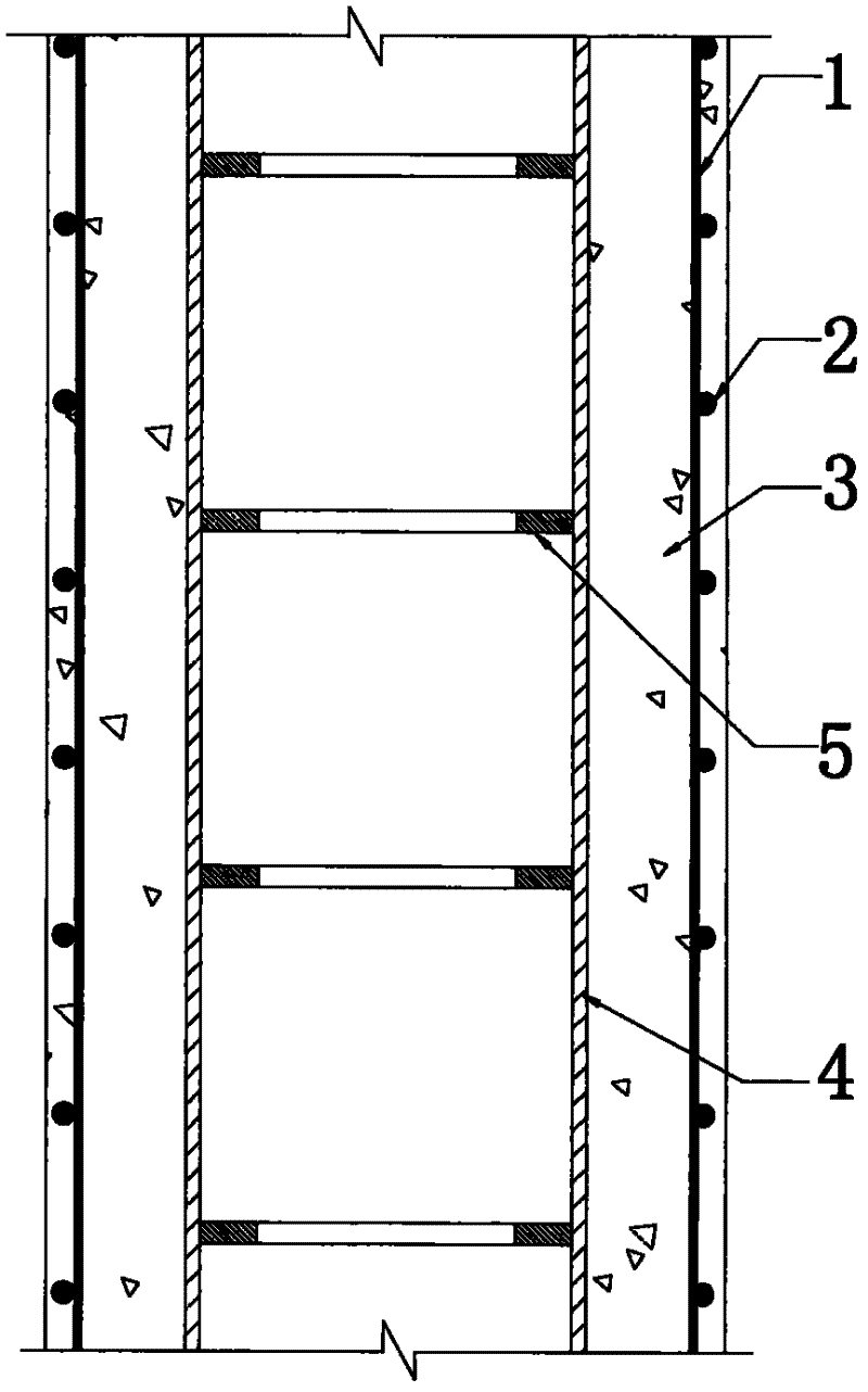
[0035] Figure 4 ~ Figure 11 The cross section of the pier and the inner steel pipe are one of circular cross section, rectangular cross section, oval cross section, round end cross section or hexagonal cross section; the pier cross section is rectangular cross section, the inner steel pipe is circular cross section; the pier cross section is Schematic diagram of cross-sectional structure of reinforced concrete hollow piers with inner steel pipes constrained by inner steel pipes with circular cross-section and inner steel pipe as rectangular cross-section; pier with hexagonal cross-section and inner steel pipe as circular cross-section.

[0036] In the specific implementation, the inner steel pipe 4 and the diaphragm 5 are processed first. The middle part of the diaphragm 5 is hollow and ring-shaped, and the cross-sectional shape is the same as that of the inner steel pipe 4. The thickness of the steel plate of the partition 5 should not be less than 5mm, and its width should ...


PUM


Abstract

The invention provides an internal steel tube confined reinforced concrete hollow pier. The pier is jointly formed by longitudinal bars (1), stirrups (2), internal steel tubes (4), diaphragms (5) and concrete (3) poured outside the internal steel tubes (4), wherein the longitudinal bars (1) and the stirrups (2) form a reinforcement cage; the concrete (3) wraps the reinforcement cage; concrete covers are arranged outside the stirrups (2); the horizontal diaphragms (5) are arranged inside the internal steel tubes (4) and are vertically arranged at intervals along the pier; the arrangement distances of the horizontal diaphragms are not greater than the minimum size of the pier section appearance; and the internal steel tubes (4) are hollow inside and confine the concrete between the internal steel tubes and the stirrups with the stirrups (2) inside and outside. The pier has the following beneficial effects that: the structure saves materials; and stressed in three directions, the side wall concrete is not easy to damage, has high bearing capacity, good ductility and good durability and is especially suitable for large load and large section high pier and bridge tower components.

Description

technical field [0001] The invention relates to a bridge pier structure, in particular to a reinforced concrete hollow bridge pier constrained by inner steel pipes. Background technique [0002] Reinforced concrete hollow pier refers to a reinforced concrete pier with a hollow interior, which is an optimized form of pier cross-section for light and economical substructure. It has the characteristics of small cross-sectional area, large cross-sectional resistance moment, light weight, good structural rigidity and bearing capacity. It is widely used in the field of roads and railways, and is mostly used for high bridge piers. Compared with the gravity-type solid bridge piers, the hollow bridge piers can generally reduce the amount of concrete by 40% to 60%. [0003] In the construction of highways and railways in mountainous areas of our country, due to the large changes in terrain, high bridge piers account for a large proportion. High bridges with a pier height of more than...

Claims


Application Information

Patent Timeline
Patent Type & Authority Applications(China)
IPC IPC(8): E01D19/02
Inventor 魏洋
Owner NANJING FORESTRY UNIV
Why Eureka
Try Eureka