

Battery mounting structure of electromotive vehicle
一种电动车辆、电池搭载的技术,应用在上部结构、下部结构、车辆部件等方向,能够解决车身扭转刚性降低、提高车身扭转刚性等问题,达到提高车身扭转刚性、提高强度、提高抗侧面碰撞性能的效果
- Summary
- Abstract
- Description
- Claims
- Application Information
AI Technical Summary
Problems solved by technology
Method used
Image

Examples
Embodiment Construction
[0029] Hereinafter, embodiments of the present invention will be described in detail with reference to the drawings.
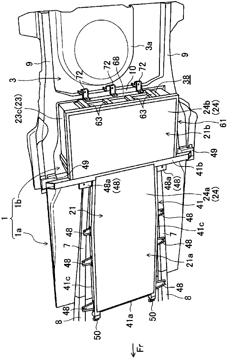
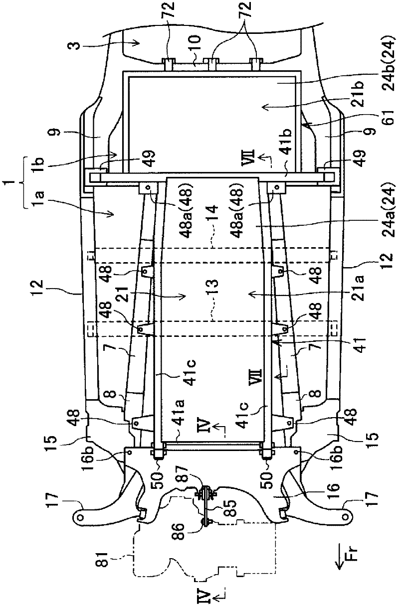
[0030] figure 1 and figure 2 It is a diagram showing an electric vehicle (an electric vehicle in this embodiment, hereinafter simply referred to as a vehicle) to which the battery mounting structure according to the embodiment of the present invention is applied. Specifically, in the figure 1 and figure 2 In , the structure of the lower side of the floor panel 1 constituting the cabin floor of the vehicle is shown. Hereinafter, the front, rear, left, right, up and down of the vehicle are simply referred to as front, rear, left, right, up and down, respectively. In addition, in Figure 1 to Figure 7 In , the vehicle front side is indicated by an arrow mark Fr.
[0031] The bottom plate 1 includes a front floor portion 1a and a rear floor portion 1b located on the rear side of the front floor portion 1a. Between the front floor portion 1a and the rear f...
PUM
 Abstract
Description
Claims
Application Information