
Antenna

An antenna and wireless signal technology, which is applied to antennas, devices that enable antennas to work in different bands at the same time, and the structural form of radiating elements, etc., can solve the problems that the antenna volume is not easy to shrink, the radiator is prone to interference, and the antenna structure is complex.

Inactive Publication Date: 2012-05-16
WISTRON CORP
View PDF2 Cites 0 Cited by
  • Summary
  • Abstract
  • Description
  • Claims
  • Application Information

AI Technical Summary

Problems solved by technology

However, the above requirements often make the structure of the antenna too complex, and the size of the antenna is not easy to reduce
In addition, interference between radiators in different frequency bands is also prone to occur

Method used


Image

  • Antenna
  • Antenna
  • Antenna

Examples


Embodiment Construction

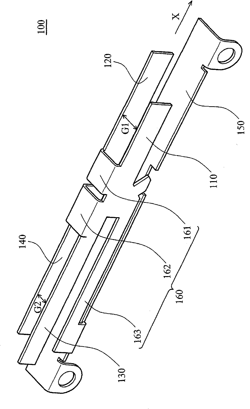
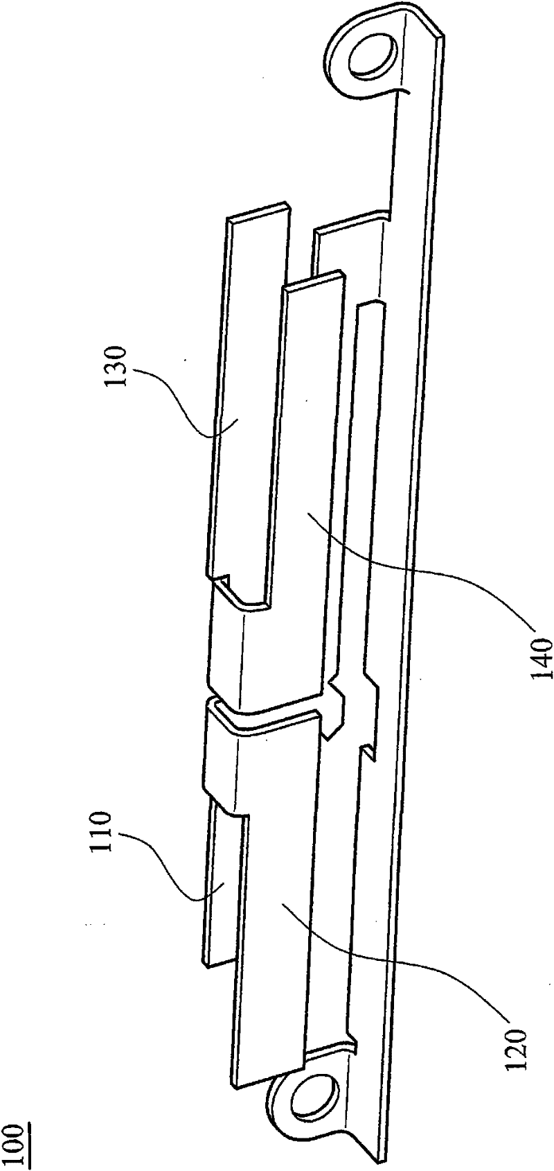
[0017] refer to Figure 1A , Figure 1B , which shows that the antenna 100 according to the embodiment of the present invention includes a grounding element 150 , a connecting element 160 , a first radiator 110 , a second radiator 120 , a third radiator 130 and a fourth radiator 140 . The connecting piece 160 is connected to the grounding piece 150 . The first radiator 110 is connected to the connecting member 160 and extends toward a first direction (X). The first radiator 110 is used for transmitting a first wireless signal. The second radiator 120 is connected to the connecting member 160 and extends toward the first direction (X). The second radiator 120 is parallel to the first radiator 110. The second radiator 120 is used to transmit a second wireless signal. Signal. The third radiator 130 is connected to the connecting member 160 and extends toward a second direction (-X). The third radiator 130 is used for transmitting a third wireless signal. The fourth radiator 14...


PUM


Abstract

The invention discloses an antenna. The antenna comprises an earthing piece, a connecting piece, a first radiating body, a second radiating body, a third radiating body and a fourth radiating body, wherein the connecting piece is connected with the earthing piece; the first radiating body is connected with the connecting piece, extends towards a first direction and transmits a first wireless signal; the second radiating body is connected with the connecting piece, extends towards the first direction, is parallel to the first radiating body and transmits a second wireless signal, the frequency of the first wireless signal is different from that of the second wireless signal, and the first radiating body and the second radiating body resonate when the antenna transmits the first wireless signal and the second wireless signal; the third radiating body is connected with the connecting piece, extends towards a second direction and transmits a third wireless signal; the fourth radiating body is connected with the connecting piece, extends towards the second direction, is parallel to the third radiating body and transmits a fourth wireless signal, the frequency of the third wireless signal is different from that of the fourth wireless signal, the first direction is opposite to the second direction, and the third radiating body and the fourth radiating body resonate when the antenna transmits the third wireless signal and the fourth wireless signal. The bandwidth of the antenna is increased.

Description

technical field [0001] The invention relates to an antenna, especially an antenna capable of increasing bandwidth. Background technique [0002] In the known antenna, in order to increase the bandwidth of the wireless signal transmitted by the antenna, it is often necessary to increase the width of the radiator, or to set an extension or a bent part on the radiator, resulting in an excessively large volume of the conventional antenna. [0003] With the increasing number of wireless communication specifications, a single antenna must be able to meet communication specifications such as WLAN, WIFI, Bluetooth, and WIMAX at the same time. However, the above requirements often result in an overly complex structure of the antenna, and the size of the antenna is not easily reduced. In addition, interference is also prone to occur between radiators in different frequency bands. Contents of the invention [0004] The present invention provides an antenna to solve the problems of ...

Claims


Application Information

Patent Timeline
Patent Type & Authority Applications(China)
IPC IPC(8): H01Q1/36H01Q5/01H01Q5/10
Inventor 周震宇
Owner WISTRON CORP
Learn More