
Optical fiber sensing system based on free-form surface off-axis reflection and measuring method

An optical fiber sensing system and off-axis reflection technology are applied in the direction of transmitting sensing components using optical devices, which can solve problems such as uncorrectable aberrations and inability to focus light, and achieve easy observation, wide wavelength range, and wide transmission bandwidth. Effect

Active Publication Date: 2021-03-02
NORTHEASTERN UNIV
View PDF6 Cites 0 Cited by
  • Summary
  • Abstract
  • Description
  • Claims
  • Application Information

AI Technical Summary

Problems solved by technology

However, non-rotationally symmetric off-axis reflective optical systems naturally have a series of asymmetric aberrations, which cannot make the light focus perfectly on one point, and these aberrations are usually not corrected by traditional spherical or aspheric surfaces
[0003] The free-form surface is a non-rotationally symmetric non-traditional optical surface, which helps to realize the design of high-performance systems with advanced indicators, compact structure, and small size, and has the ability to correct asymmetric aberrations of off-axis systems. At present, the existing technology There is no precedent for applying free-form surfaces to optical fiber sensing systems; the four-wave mixing process originates from the nonlinear response of bound electrons in the medium to the external electromagnetic field, and is a phenomenon of mutual modulation of light waves in nonlinear optics

Method used


Image

  • Optical fiber sensing system based on free-form surface off-axis reflection and measuring method
  • Optical fiber sensing system based on free-form surface off-axis reflection and measuring method
  • Optical fiber sensing system based on free-form surface off-axis reflection and measuring method

Examples


Embodiment

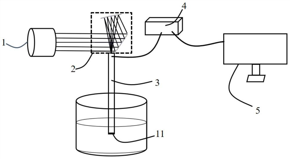
[0033] A four-wave mixing fiber optic sensing system based on free-form surfaces, such as figure 1 As shown, it includes: a continuous laser 1, an off-axis two-reflection optical system 2 based on a free-form surface, an optical fiber sensor 3, a spectrometer 4 connected to the output end of the optical fiber sensor, and a host computer 5 connected to the spectrometer; The laser light is coupled to the fiber optic sensor after being reflected and focused by an off-axis two-mirror optical system based on a free-form surface.

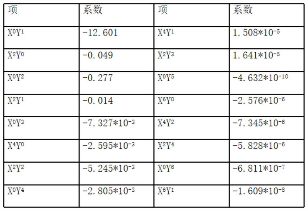
[0034] The off-axis two-mirror optical system based on a free-form surface includes a primary reflector and a secondary reflector. The primary reflector 12 is a hyperboloid with a radius of -60.7mm and an aspheric coefficient of -6.084. The secondary reflector 13 is an XY polynomial free-form surface, and it is a 6-degree free-form surface with a radius of 20mm and an aspheric coefficient of -8.399. The XY polynomial coefficients are as follows image 3 ...


PUM

PropertyMeasurementUnit
Radius rangeaaaaaaaaaa
Diameteraaaaaaaaaa
Lengthaaaaaaaaaa

Abstract

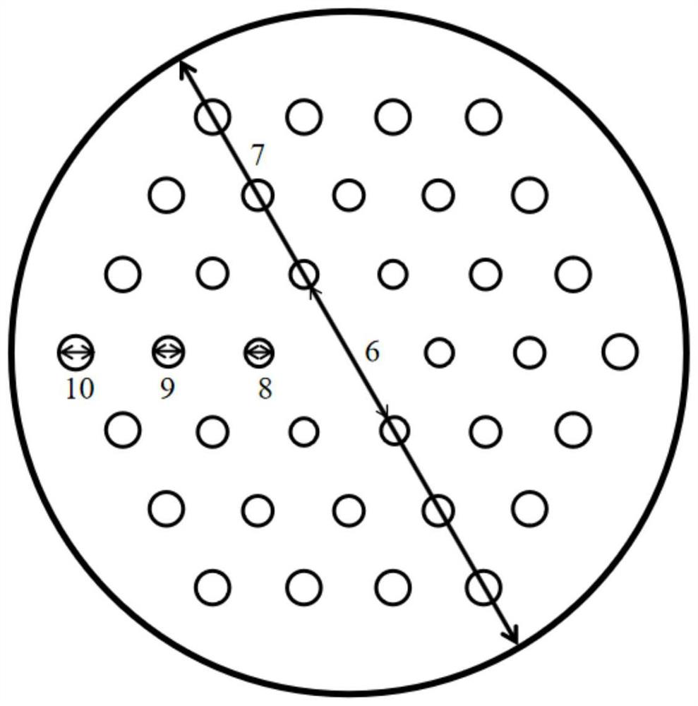
The invention provides an optical fiber sensing system based on free-form surface off-axis reflection and a measuring method. The sensing system comprises a continuous laser, an off-axis two-mirror optical system based on a free-form surface, an optical fiber sensor, a spectrograph connected with the output end of the optical fiber sensor, and an upper computer connected with the spectrograph. Laser emitted by the continuous laser is coupled to the optical fiber sensor after being reflected and focused by the off-axis two-mirror optical system based on the free-form surface, the optical fibersensor is a chalcogenide photonic crystal optical fiber sensor, a plurality of air holes are formed in a cladding of the optical fiber sensor, and the air holes are evenly distributed with a fiber core of the sensor as the center. The off-axis free-form surface is applied to the four-wave mixing optical fiber sensing system, a traditional coaxial-based optical fiber detection device is changed, and the coupling efficiency is improved; the sensing mechanism is based on the change of four-wave mixing parameter gain bandwidth, and the practicability and the sensing sensitivity of the optical fiber sensing system are improved.

Description

technical field [0001] The invention relates to the technical field of optical design, in particular to an optical fiber sensing system and measurement method based on free-form surface off-axis reflection. Background technique [0002] With the rapid development of industrial production, the requirements for optical fiber sensing systems with high sensitivity, miniaturization and strong practicability are getting higher and higher. The traditional optical fiber sensing system is based on the coaxial optical path, and it cannot carry out effective measurement for scenes that require optical path turning, such as oil well detection, ocean detection, tunnel detection, etc. Nowadays, off-axis reflective optical systems are attracting more and more attention of researchers. Such systems are generally composed of multiple off-axis mirrors, which do not have global rotational symmetry and do not have a unified optical axis. However, a non-rotationally symmetric off-axis reflecti...

Claims


Application Information

Patent Timeline
IPC IPC(8): G01D5/353
CPCG01D5/353
Inventor 程同蕾陈晓雨李曙光闫欣张学楠王方
Owner NORTHEASTERN UNIV
Learn More