Dielectric constant measuring device based on waveguide structure

A dielectric constant and measuring device technology, which is applied in the field of dielectric constant measuring devices based on waveguide structures, can solve the problems of signal transmission interference, impossibility, and high cost, and achieve simplified calculation process, high precision and high precision Effect

Pending Publication Date: 2022-07-19
CHINA WEST NORMAL UNIVERSITY
View PDF0 Cites 0 Cited by
  • Summary
  • Abstract
  • Description
  • Claims
  • Application Information

AI Technical Summary

Problems solved by technology

[0003] Although there are various methods for measuring the dielectric constant, the change of temperature will inevitably affect the dielectric properties of the material, thereby affecting the information transmission performance of the antenna on the shielding cover, and causing great interference to signal transmission, but it cannot be done once and for all. , Different systems measure different materials, and different measurement methods are used at different frequencies. There are few solutions for measuring dielectric constant under high-power microwaves, and the general cost is expensive and the structure is complicated. It is impossible to realize complex measurement while heating. Dielectric constant real-time measurement function, for this reason, the present invention introduces a kind of dielectric constant measurement device based on waveguide structure

Method used


Image

  • Dielectric constant measuring device based on waveguide structure
  • Dielectric constant measuring device based on waveguide structure
  • Dielectric constant measuring device based on waveguide structure

Examples


Embodiment Construction

[0026] The technical solutions in the embodiments of the present invention will be clearly and completely described below with reference to the accompanying drawings in the embodiments of the present invention. Obviously, the described embodiments are only a part of the embodiments of the present invention, but not all of the embodiments. Based on the embodiments of the present invention, all other embodiments obtained by those of ordinary skill in the art without creative efforts shall fall within the protection scope of the present invention.

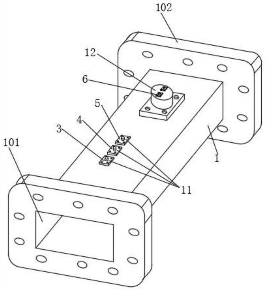
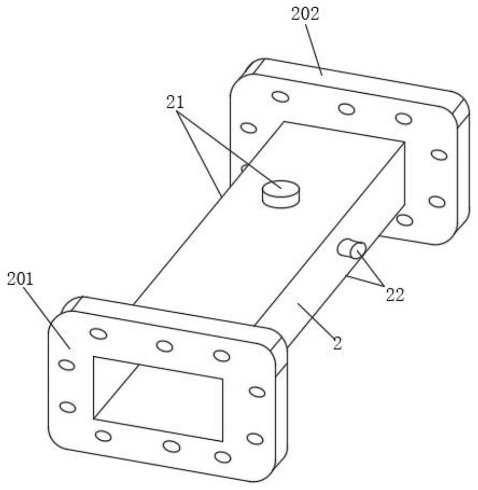
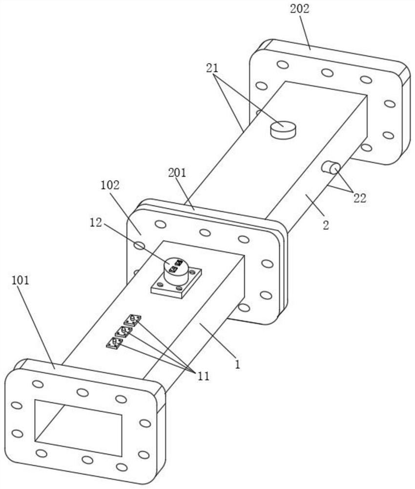
[0027] see Figure 1-6 , a dielectric constant measurement device based on a waveguide structure,

[0028] Step 1: Carry out modeling and simulation analysis in CST, adjust the model structure, and test the rationality of the data, make devices according to the simulation model and build an experimental platform,

[0029]Step 2: First calibrate the reflectometer 1, and calculate the calibration constant of the reflectometer 1. It is ...


PUM


Abstract

The invention relates to the technical field of microwave measurement, and discloses a dielectric constant measuring device based on a waveguide structure, which comprises a six-port reflectometer, a rectangular waveguide is fixedly mounted on the upper surface of the six-port reflectometer, and a seventh port is fixedly mounted on the side surface of the rectangular waveguide. According to the invention, a directional coupler is formed by coupling two paths of microwave transmission lines, a certain proportion of microwaves input from a main line are coupled to an auxiliary line, a rectangular waveguide is provided with a hole, and a cuboid metal strip is placed between the upper side of the small hole and an upper cover plate. Therefore, a hole is formed in the wide surface of the rectangular waveguide, microwaves are coupled to the strip line through the small hole, then the microwaves are transmitted to the two ends of the strip line to be connected with the coaxial line, and the microwaves are transmitted to the power meter through the coaxial line, so that the waveguide-strip line-coaxial line type directional coupler is formed, and the aim of greatly reducing the complexity and the cost of the system is fulfilled.

Description

technical field [0001] The invention relates to the technical field of microwave measurement, in particular to a dielectric constant measurement device based on a waveguide structure. Background technique [0002] The application of microwave is mainly in the application of information transmission and microwave energy. Microwave measurement technology is also one of the main applications of microwave. It is the basis and important part of microwave applications. Electromagnetic materials are widely used in civil, industrial and national defense fields. Its electromagnetic parameters have an important influence on the performance and indicators of the device. Among them, the dielectric constant is the most important parameter in the electromagnetic parameters. Therefore, it is particularly important to measure the dielectric constant of the material. There are many methods for measuring the dielectric constant, which have spread throughout the industry. , civil and national ...

Claims


Application Information

Patent Timeline
Patent Type & Authority Applications(China)
IPC IPC(8): G01R27/26
CPCG01R27/2623
Inventor 洪涛种传印
Owner CHINA WEST NORMAL UNIVERSITY
Why Eureka
Try Eureka