Built-in type antenna displayer

A display, built-in technology, applied to antennas, antenna arrays, antenna components, etc., can solve problems such as broken display panels, disconnected solder joints of coaxial cables, and increased computer thickness.

Inactive Publication Date: 2012-05-23
高本蓉
View PDF3 Cites 6 Cited by
  • Summary
  • Abstract
  • Description
  • Claims
  • Application Information

AI Technical Summary

Problems solved by technology

[0007] The main purpose of the present invention is to provide a display with a built-in antenna, forming a non-coplanar antenna on the metal frame of the display, which can simultaneously solve the existing cost of installing additional antennas and reduce the length, width and height of the additional antenna.
[0008] Another object of the present invention is to provide a display with a built-in antenna, which can avoid the design of the antenna feed point on the front or rear side of the display panel, which will increase the thickness of the computer and cause welding of the coaxial cable. The point is disconnected due to external force or the display panel is broken due to coaxial cable extrusion

Method used


Image

  • Built-in type antenna displayer
  • Built-in type antenna displayer
  • Built-in type antenna displayer

Examples


Embodiment Construction

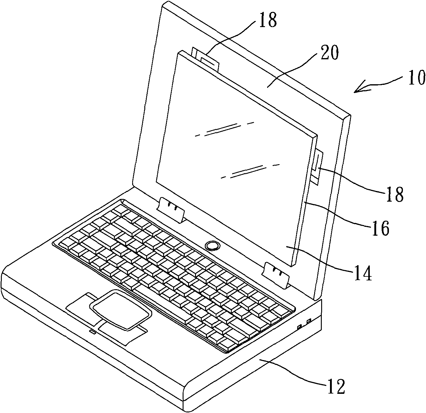
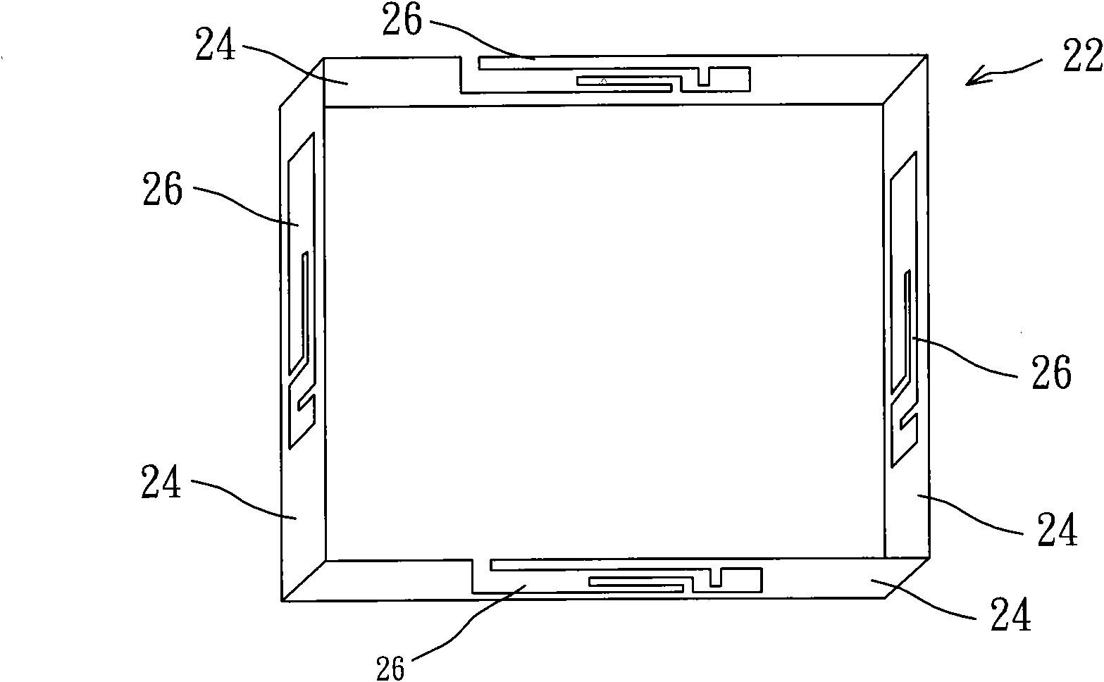
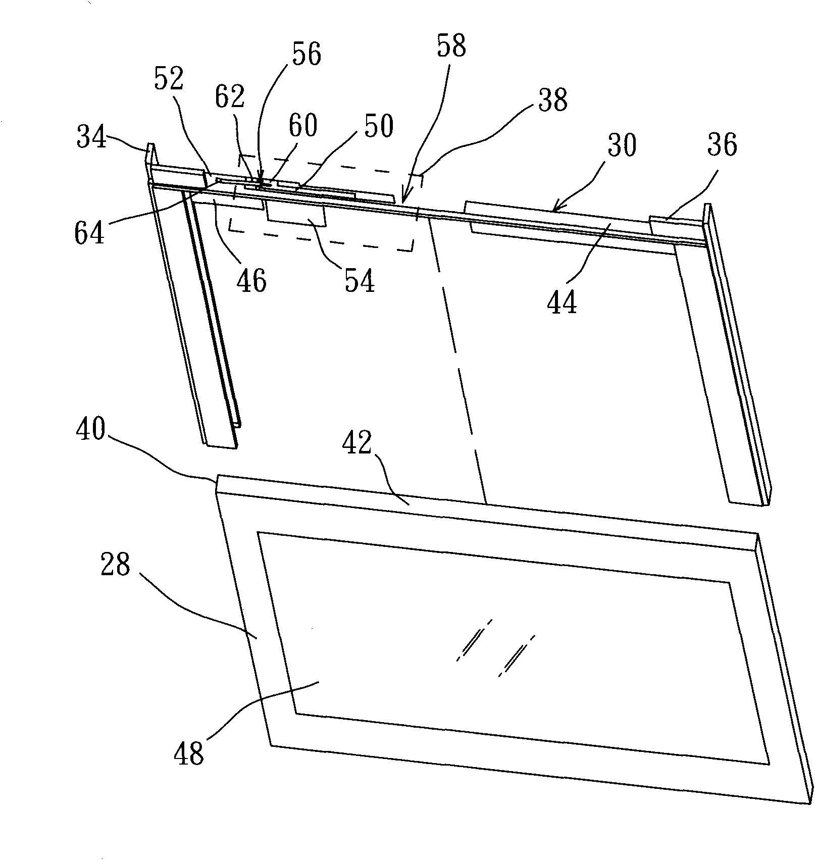
[0024] In response to the current trend of thinner and lighter notebook computers, and considering that the existing antenna is easily affected by the metal bracket next to the display and the dielectric constant of the display panel and the plastic cover assembled on it, the frequency deviation of the resonant frequency is affected Therefore, the present invention adopts a special design with a large bandwidth of the antenna. In addition to being applicable to thinner displays, it can also avoid excessive influence due to different fixing methods of metal pillars. Please also refer to image 3 and Figure 4 , the display includes a display panel 28, a metal frame 30, symmetrical first metal pillars 34 and second metal pillars 36, and at least one first antenna 38, and the outer side 40 of the display panel 28 has a mounting surface 42, wherein the display panel 28 The thickness is preferably less than 5 centimeters (mm). The metal frame 30 is fixed on the outer side 40 of t...


PUM


Abstract

A built-in type antenna displayer, formed by at least an antenna integrally on a metal frame, and said metal frame is fixed onto an outer edge of a display panel, on said outer edge of said display panel is provided with an installation surface. Said metal frame is provided with a first sidewall, and a second sidewall connected vertically to said first sidewall, so as to form an L-shape structure. On said first sidewall is formed a signal feed-in terminal and a ground terminal, and that are both located on said installation surface. On said second sidewall is provided with a resonance radiator, that is connected vertically to said installation surface, such that said resonance radiator is connected vertically to said signal feed-in terminal to form a non-coplanar structure having a WLAN triple band antenna.

Description

technical field [0001] The present invention relates to a display, in particular to a metal frame in which a non-coplanar antenna structure covering three bands of a wireless area network (WLAN) is integrally formed. Background technique [0002] With the advancement of technology, the use of notebook computers has become quite common and has become an indispensable equipment in the life and work of modern people. Therefore, the functionality and convenience of using the notebook computer are closely related to the user's work efficiency or life and entertainment. In addition, with the advent of the wireless network era, all notebook computers will be equipped with antennas to achieve wireless transmission functions. While configuring the antenna, it is also necessary to take into account the user's requirements for a notebook computer that is light, thin, and small, so that the antenna configuration becomes an important issue. [0003] In the prior art, in order to enable...

Claims


Application Information

Patent Timeline
Patent Type & Authority Applications(China)
IPC IPC(8): G06F1/16H01Q1/22H01Q1/36H01Q5/01H01Q21/00H01Q5/10
CPCH01Q21/28H01Q1/2266G06F1/1698H01Q5/0055H01Q5/364
Inventor 高本蓉
Owner 高本蓉
Why Eureka
Try Eureka