Synchronous guide of a push member and piece of furniture

A technology of guiding devices and moving elements, which is applied in furniture parts, household appliances, household refrigeration devices, etc.

Active Publication Date: 2012-05-23
PAUL HETTICH
View PDF3 Cites 26 Cited by
  • Summary
  • Abstract
  • Description
  • Claims
  • Application Information

AI Technical Summary

Problems solved by technology

[0005] Problems can arise with this arrangement since, when installing the synchronous guide afterwards, the push element must first be removed in order to fix the gear in the rear area of ​​the push element

Method used


Image

  • Synchronous guide of a push member and piece of furniture
  • Synchronous guide of a push member and piece of furniture
  • Synchronous guide of a push member and piece of furniture

Examples


Embodiment Construction

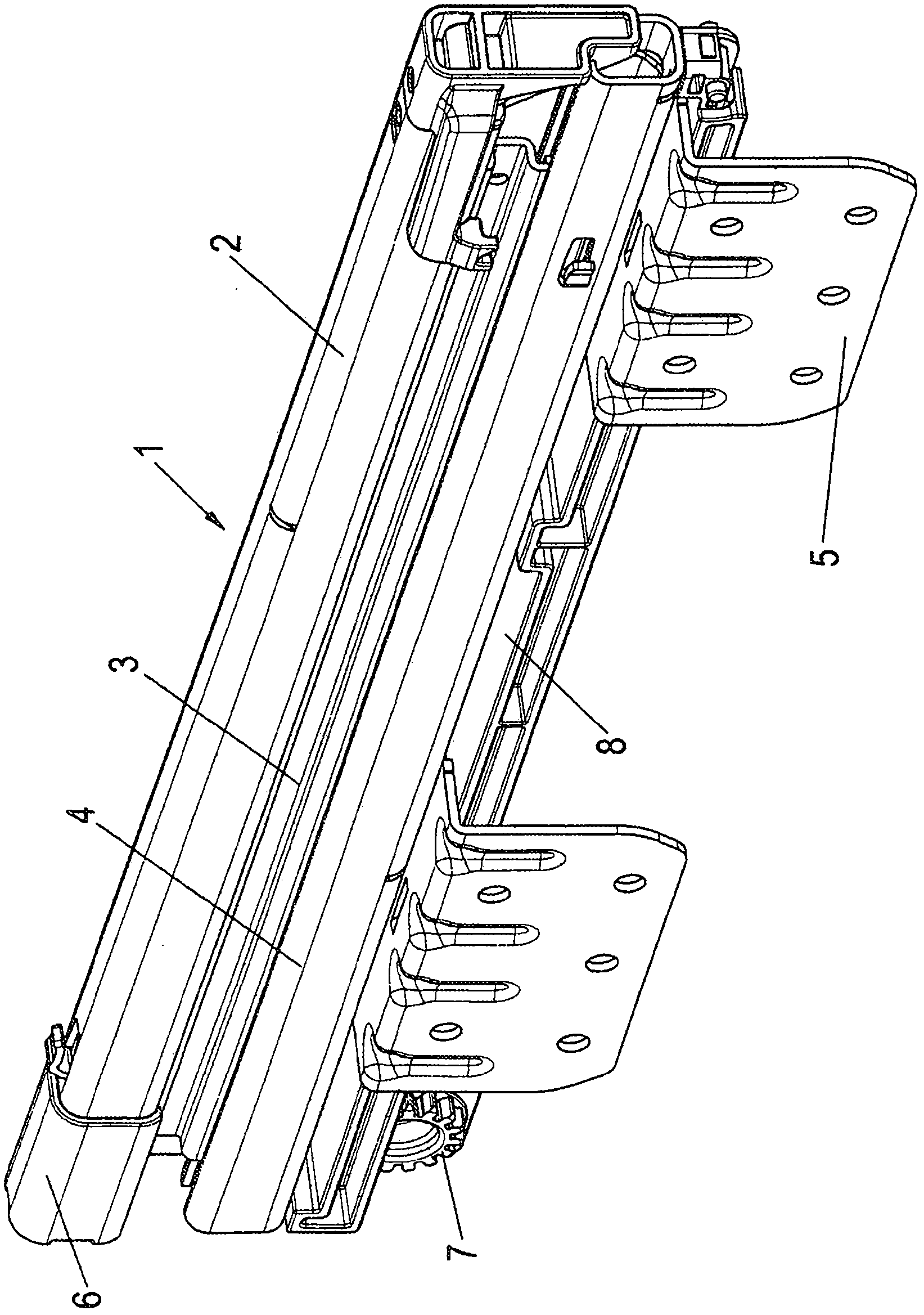
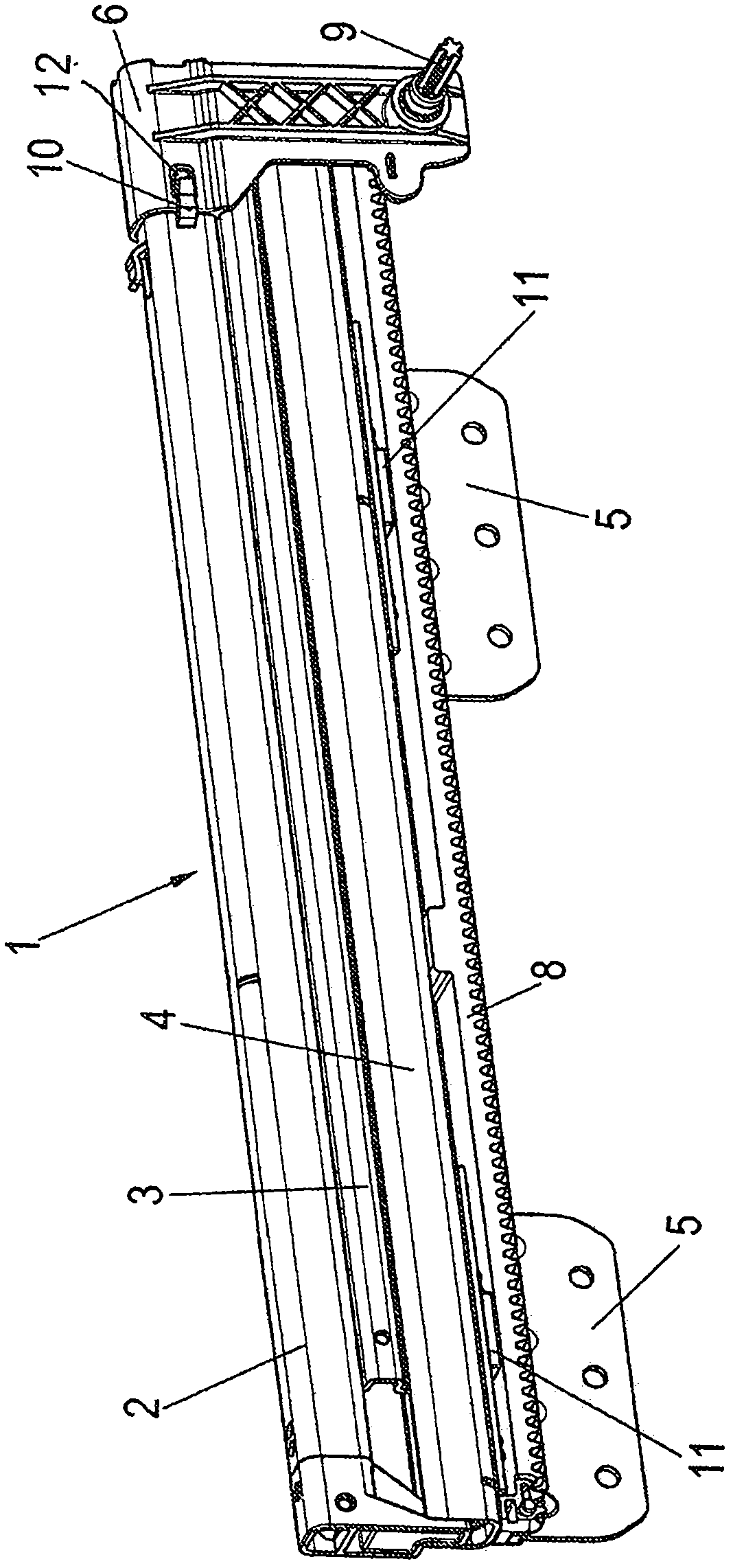
[0033] exist figure 1 and figure 2 shows a pull-out guide provided with the reference number 1, which pull-out guide has an embodiment of a synchronous guide arranged thereon, which is used for example in Figure 8 The push element 25 shown in FIG. 1 is mounted displaceably in the main body 24 (shown only schematically). The main body 24 may be residential furniture, office furniture or even kitchen furniture, a kitchen appliance, such as a refrigerator. The pull-out guiding device includes a guide rail 4 fixed on the main body and a slide rail 2 that can move on the guide rail 4 .

[0034] In order to be able to pull out completely, in the pull-out guide device 1 , an intermediate rail 3 extending the pull-out amount can be arranged between the guide rail 4 and the slide rail 2 .

[0035] In order to illustrate the working principle of the synchronous guide device, in Figures 8 to 12 shows the different positions of the pull-out guide 1 with the synchronizing guide fast...


PUM


Abstract

Synchronous guide of a push member (25) mounted in a body (24) of a piece of furniture or household appliance by way of pullout guides (1), comprising two stationary toothed racks (8), which are located opposite to each other and associated with a side member of the body, and into which gear wheels (9) engage that are interconnected via coupling rods (26), wherein the gear wheels (9) are mounted in a stationary manner on the guide rails (2) of the pullout guides (1).

Description

technical field [0001] The invention relates to a synchronous guide for pushing elements mounted in the body of a piece of furniture or a household appliance by means of a pull-out guide as stated in the preamble of claim 1 and to a device as stated in the preamble of claim 18 the above-mentioned furniture or household appliances. Background technique [0002] In order to ensure the same movement of the push element on both sides, a synchronous guide is used, which is configured as a rack gear, wherein a toothed rack is respectively fastened on opposite sides of the main body, and a rack arranged behind the push element An associated gear in the region meshes with the rack. Skewing of the displacement element is thus effectively prevented when the displacement element is pulled out or pushed in. [0003] The gears are non-rotatably connected to each other by connecting rods to achieve synchronous rolling of the gears. [0004] In such a synchronous guide, the toothed whee...

Claims


Application Information

Patent Timeline
Patent Type & Authority Applications(China)
IPC IPC(8): A47B88/04
CPCF25D23/067A47B2210/0078A47B2210/17A47B88/04F25D25/025A47B88/45A47B88/493Y10T74/18808A47B88/43A47B88/487A47B88/40A47B88/447
Inventor J·马特斯H·克尼克尔
Owner PAUL HETTICH
Why Eureka
Try Eureka