Hermetic compressor
A compressor and airtight technology, which is applied in the direction of mechanical equipment, machines/engines, liquid variable displacement machines, etc., can solve the problems of increasing the cost of compressors, achieve the effect of reducing the number of parts and improving poor assembly
- Summary
- Abstract
- Description
- Claims
- Application Information
AI Technical Summary
Problems solved by technology
Method used
Image

Examples
Embodiment approach 1
[0033] Hereinafter, embodiments of the present invention will be described with reference to the drawings. In addition, this invention is not limited to this embodiment.
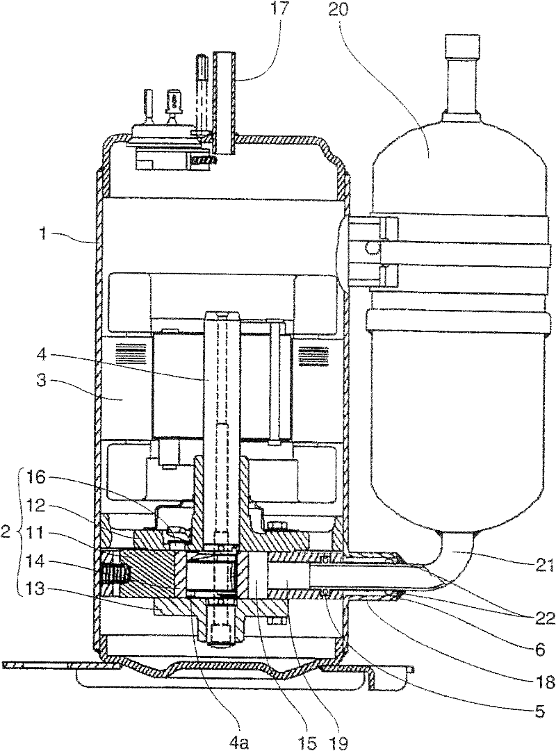
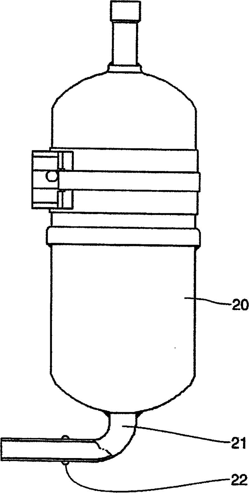
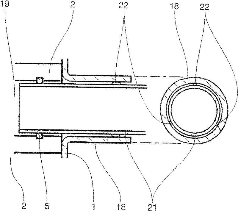
[0034] figure 1 It is a longitudinal sectional view of a hermetic compressor according to Embodiment 1 of the present invention, figure 2 is a side view of the accumulator for the hermetic compressor, image 3 It is an enlarged sectional view of the main part of the hermetic compressor.
[0035] First, use Figure 1 to Figure 3 , the overall structure of the hermetic compressor in this embodiment will be described.
[0036] Such as figure 1 As shown, the hermetic compressor of this embodiment has a compression mechanism unit 2 and a motor unit 3 inside a hermetic container 1 . The compression mechanism part 2 includes: a cylinder 11 having a cylindrical space; an upper bearing 12 closing the upper end surface of the cylindrical space of the cylinder 11; a lower bearing 13 closing the lower end surfa...
Embodiment approach 2
[0050] Figure 4 It is a cross-sectional view showing a protrusion provided on an inner pipe of an accumulator used in a hermetic compressor according to Embodiment 2 of the present invention. In addition, the basic structure of Embodiment 2 is the same as figure 1 The same, so the description is omitted.
[0051] Such as Figure 4 As shown, in the present embodiment, protrusions 23 and 24 that are staggered in the longitudinal direction are provided on the outer peripheral portion of the inner tube 21 of the accumulator 20 .
[0052] In this way, by making the protrusion 23 and the protrusion 24 stagger in the longitudinal direction, when assembling, the protrusion 23 provided on the lower side is first inserted into the flange portion 18, and then the protrusion 23 provided on the lower side is used as a fulcrum to insert the protrusion provided on the upper side. 24 is inserted into the flange portion 18, so that the inner tube 21 can be smoothly inserted into the flang...
Embodiment approach 3
[0054] Figure 5 It is a cross-sectional view showing a protrusion provided on an inner pipe of an accumulator used in a hermetic compressor according to Embodiment 3 of the present invention.
[0055] Such as Figure 5 As shown, in the present embodiment, the same effects as in the first embodiment can be obtained by providing the annular protrusion 25 on the outer peripheral portion of the inner tube 21 of the accumulator 20 .
[0056]In addition, the purpose of the present invention can be achieved when there is at least one ring-shaped protrusion 25, but two or more are preferable. The gap between the inner tube 21 and the burring portion 18 can be made more uniform by arranging a plurality of annular protrusions 25 staggered in the longitudinal direction of the inner tube 21 .
[0057] The tubular protrusion 25 can be formed by clamping the inner tube 21 with jigs each having a concave portion opposite to that of the protrusion 22 and bringing the two jigs closer togeth...
PUM
 Abstract
Description
Claims
Application Information
 - R&D Engineer
- R&D Manager
- IP Professional
- Industry Leading Data Capabilities
- Powerful AI technology
- Patent DNA Extraction
Browse by: Latest US Patents, China's latest patents, Technical Efficacy Thesaurus, Application Domain, Technology Topic.
© 2024 PatSnap. All rights reserved.Legal|Privacy policy|Modern Slavery Act Transparency Statement|Sitemap