Connection device for a plastic tube

A connection device, plastic pipe technology, applied in the direction of hose connection device, pipe connection arrangement, pipe/pipe joint/pipe fitting, etc., can no longer ensure the holding claw pressing force, damage the elastic function of the support ring, installation cost and other problems, to achieve the effect of eliminating wrong installation, reducing clamping tendency, and simple installation

Active Publication Date: 2012-05-23
KE KELIT KUNSTSTOFFWERK GMBH
View PDF7 Cites 17 Cited by
  • Summary
  • Abstract
  • Description
  • Claims
  • Application Information

AI Technical Summary

Problems solved by technology

However, this structure has some disadvantages in terms of its functionality
As a result, not only is the installation time consuming, but there is also the risk that, when the plastic tube is slid onto the connection piece, the elastic support ring is pressed out of its receiving gr

Method used


Image

  • Connection device for a plastic tube
  • Connection device for a plastic tube
  • Connection device for a plastic tube

Examples


Embodiment Construction

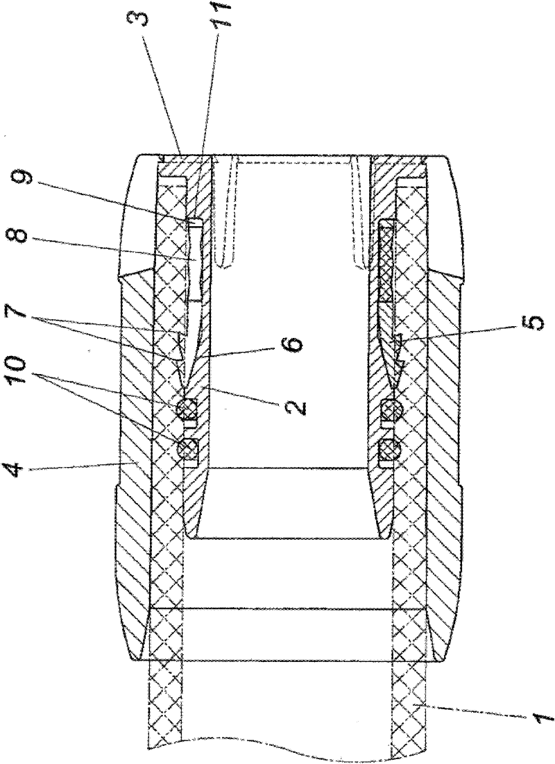
[0016] according to figure 1 , The connecting device for the plastic pipe 1 shown in dashed lines has a connecting joint 2 for receiving the plastic pipe 1 with a stop flange 3, and a sleeve 4 surrounding the plastic pipe 1 acts on the stop in a shear-resistant manner. Stop the flange.

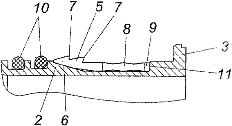
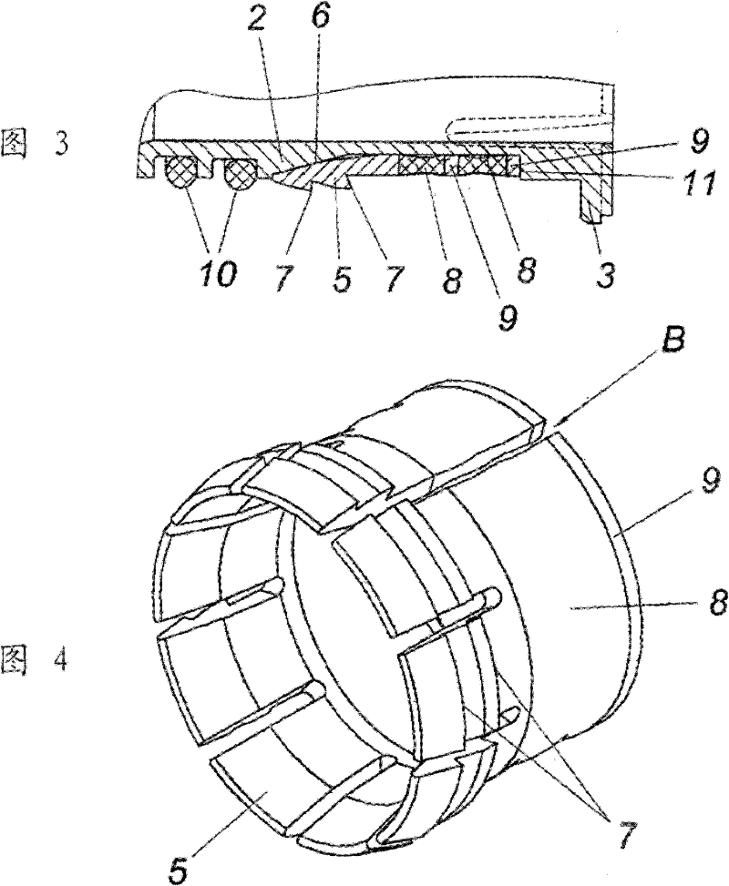
[0017] In order to clamp the plastic tube 1 between the connection joint 2 and the sleeve 4, an expansion ring 5 is supported on the connection joint 2, and the expansion ring interacts with the outer cone 6 of the connection joint 2. The device is designed in such a way that the expansion ring 5 formed on the retaining pawl 7 protruding radially toward the outside of the plastic tube 1 is elastically supported on the stop 11 of the connection joint 2 via the elastic spring washer 8 and the support ring 9. The expansion ring 5, the spring washer 8 and the support ring 9 form a structural unit composed of several individual parts combined in a shear-resistant manner.

[0018] If the plastic tube 1 ...


PUM


Abstract

The invention relates to a connection device for a plastic tube (1), comprising a connection nipple (2) that receives the plastic tube (1) and forms an outer cone (6) widening towards the free nipple end. An expansion ring (5) that can be slid over the outer cone (6) and comprises outwardly protruding retaining claws (7) is provided between the outer cone and an axial abutment (11), said expansion ring being supported on the axial abutment (11) of the connection nipple (2) by means of a supporting ring (9). Said device also comprises a sleeve (4) surrounding the plastic tube (1) that has been pushed onto the connection nipple (3) and gripping in a traction-resistant manner onto an abutment flange (3) of the connection nipple. In order to create advantageous assembly conditions, a rubber-elastic spring ring (8) is arranged between the expansion ring (5) and the supporting ring (9). The expansion ring (5), the supporting ring (10) and the spring ring (8) are interconnected in a shear-resistant manner.

Description

Technical field [0001] The invention relates to a connecting device for plastic pipes. The connecting device is provided with a connecting joint for receiving the plastic pipe and a sleeve which is tensile-jointed on the stop flange of the connecting joint and surrounds the plastic pipe on the connecting joint. Barrel, wherein the connecting joint forms an outer cone that expands toward the free joint end, and an expansion ring slidably sleeved on the outer cone is arranged between the outer cone and the axial stop, and the expansion ring has an outwardly convex The extended retaining claw is supported on the axial stop of the connection joint through a supporting ring. Background technique [0002] In this type of known connection device (AT410706B), the plastic tube is sleeved on the connection joint, which supports an expansion ring with retaining claws protruding outward in the area of ​​the outer cone, so that the plastic The tube slides over an expansion ring located in th...

Claims


Application Information

Patent Timeline
IPC IPC(8): F16L33/00
CPCF16L47/12F16L37/0925F16L37/0926
Inventor E.拉奇曼
Owner KE KELIT KUNSTSTOFFWERK GMBH
Why Eureka
Try Eureka