Edge-light-type illuminating device, liquid crystal display device, and television receiver

A technology for a liquid crystal display device and a TV receiving device is applied in the field of edge light type lighting devices, which can solve the problems of insufficient light quantity and the like, and achieve the effect of allowing thermal expansion.

Inactive Publication Date: 2012-05-23
SHARP KK
View PDF6 Cites 11 Cited by
  • Summary
  • Abstract
  • Description
  • Claims
  • Application Information

AI Technical Summary

Problems solved by technology

In a large-sized liquid crystal display device, the amount of light may not be sufficient in a configuration in which light-emitting diodes are arranged on only one side of the light guide plate as described above.

Method used


Image

  • Edge-light-type illuminating device, liquid crystal display device, and television receiver
  • Edge-light-type illuminating device, liquid crystal display device, and television receiver
  • Edge-light-type illuminating device, liquid crystal display device, and television receiver

Examples


Embodiment Construction

[0084] Hereinafter, with reference to the drawings, embodiments of the edge-lit lighting device, liquid crystal display device, and television receiver of the present invention will be described. However, the present invention is not limited to the embodiments exemplified in this specification.

[0085] [Edge lighting device]

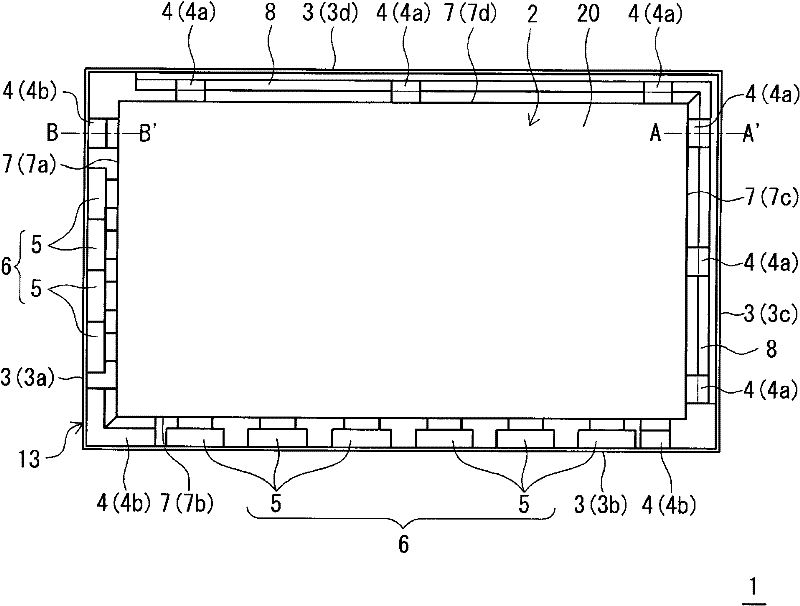
[0086] Edge reference Figure 1 ~ Figure 4 , While describing an embodiment of the edge-light illuminating device. figure 1 It is an explanatory diagram schematically showing a schematic configuration of an edge light illuminating device 1 according to an embodiment. Such as figure 1 As shown, the edge-light lighting device 1 includes a light guide plate 2, a wall 3, a holding portion 4, and a point light source row 6 including a plurality of point light sources 5. In addition, the edge-light illuminating device 1 also includes an optical sheet, a reflective sheet, etc., but for convenience of description, figure 1 Optical sheets, reflective sheets, etc...


PUM


Abstract

Provided is an edge-light-type illuminating device wherein formation of a space between a point light source and the end surface of a light guide plate is suppressed, and thermal expansion of the light guide plate is allowed. The edge-light-type illuminating device (1) illuminates a liquid crystal panel from the rear surface, and is provided with: the substantially rectangular light guide plate (2); walls (3) surrounding the light guide plate (2); a plurality of holding sections (4), which are disposed between the respective end surfaces (7) of the light guide plate (2) and the walls (3), and hold the light guide plate (2) inside of the walls (3); and point light source rows (6, 6), each of which is composed of a plurality of point light sources (5) and are disposed along the respective end surfaces (7a, 7b) on the adjacent two sides of the light guide plate (2). Among the holding sections (4), the holding section (4) that faces the point light source row (6) with the light guide plate (2) therebetween is composed of an elastic holding section (4a) having an elastic force.

Description

Technical field [0001] The present invention relates to an edge light illuminating device, a liquid crystal display device and a television receiving device, in particular to an edge light illuminating device whose light source includes point light sources such as light emitting diodes, a liquid crystal display device including the edge light illuminating device and the liquid crystal display device TV receiver. Background technique [0002] A transmissive liquid crystal display device having a liquid crystal panel that displays video, text information, etc., includes an illuminating device (so-called backlight) that irradiates the liquid crystal panel with light from the back side. As such an illuminating device, an edge-light type illuminating device is known. The edge-light type illuminating device includes: a plate-shaped light guide plate containing a transparent material such as acrylic resin; and a light source, which includes a cooler arranged along the end surface of the...

Claims


Application Information

Patent Timeline
Patent Type & Authority Applications(China)
IPC IPC(8): F21S2/00F21V17/00G02F1/1333G02F1/13357H04N5/66F21Y101/02
CPCG02F2201/46G02B6/0091G02F2001/133325G02B6/0068G02F1/133615G02F2001/133322G02B6/0073G02B6/0083G02B6/0035G02B6/0061G02F2001/133317G02F1/13452G02F1/133322G02F1/133325G02F1/133317
Inventor 鹰田良树
Owner SHARP KK
Why Eureka
Try Eureka