
Burners for gas turbine power plant burners

A gas turbine and burner technology, applied to gas fuel burners, combustion using liquid fuels and gaseous fuels, burners, etc., to achieve reliable ignition conditions, allow thermal expansion, and minimize the risk of wear and oxidation

Active Publication Date: 2022-05-13
ANSALDO ENERGIA SWITZERLAND AG
View PDF7 Cites 0 Cited by
  • Summary
  • Abstract
  • Description
  • Claims
  • Application Information

AI Technical Summary

Problems solved by technology

In this case, uneven axial displacement of the bore supporting the flare may occur with excessive wear of the liner wall

Method used


Image

  • Burners for gas turbine power plant burners
  • Burners for gas turbine power plant burners
  • Burners for gas turbine power plant burners

Examples


Embodiment Construction

[0033] In conjunction with the accompanying drawings, the technical content and detailed description of the present invention are hereinafter described according to preferred embodiments, and are not intended to limit the implementation scope thereof. Any equivalent changes and modifications made in accordance with the appended claims are all covered by the present invention.

[0034] The present invention will now be described in detail with reference to the accompanying drawings.

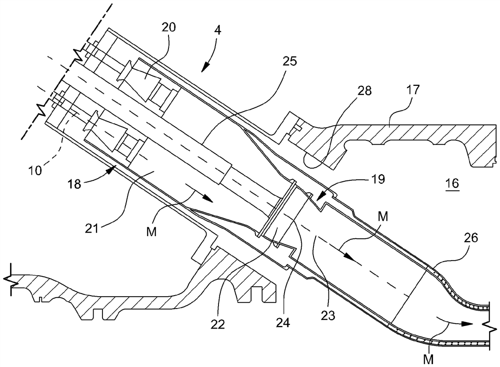
[0035] see now figure 1 , figure 1 is a schematic diagram of a gas turbine for a power plant, which may be provided with a burner according to the invention. in particular, figure 1 A gas turbine 1 having an axis 9 and comprising a compressor 2 , a combustor section 4 and a turbine 3 is disclosed. As is known, the compressor comprises an inlet fed by ambient air, which, once compressed, leaves the compressor 2 and enters the chamber 16 , ie the volume defined by the casing 17 . From a plenum...


PUM


Abstract

A burner for a combustor in a gas turbine power plant, the burner having an axis and comprising an inlet fed by compressed air; an outlet facing the combustion chamber; extending along the axis and having a tip with a band approximately at the outlet of the burner A spray gun in the downstream part of the spray gun; at least a fuel injector for injecting fuel in the air stream; an annular cavity between at least the downstream part of the spray gun and the casing; an axial vortex for generating air or a mixture of air and fuel in the annular cavity swirling swirl generator; wherein the burner also includes at least a spark generator at the tip of the lance.

Description

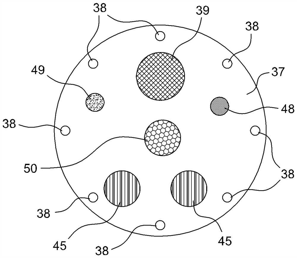
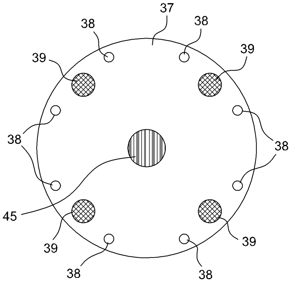
[0001] Cross References to Related Applications [0002] This application claims priority from Russian Patent Application No. 2017145773 filed on December 26, 2017, the disclosure of which is incorporated by reference. technical field [0003] The invention relates to a burner for a gas turbine of a power station. In particular, the invention relates to a premix burner for sequential can combustors of gas turbines in power plants. [0004] Furthermore, the invention relates to a sequential can combustor comprising a premix burner as described above, and a gas turbine for a power plant comprising such a sequential can combustor. Background technique [0005] As is known, a gas turbine assembly for a power plant (hereinafter simply a gas turbine) comprises a rotor with an axis and provided with an upstream compressor section, a combustor section and a downstream turbine section. The terms downstream and upstream refer to the direction of the main gas flow through the gas tu...

Claims


Application Information

Patent Timeline
Patent Type & Authority Patents(China)
IPC IPC(8): F23R3/28F23R3/38F23R3/42F23R3/58F23D14/02
CPCF23R3/286F23R3/38F23R3/42F23R3/58F23D14/02F02C7/264F23C1/08F23C2900/07002F23C2900/07021F23D2207/00F23D2900/00008F23R2900/03341F23R3/34
Inventor C.高普M.T.莫勒A.A.奥库内夫H.P.科诺佛
Owner ANSALDO ENERGIA SWITZERLAND AG
Learn More