Refrigerator
A technology for refrigerators and storage rooms, which is applied to household refrigeration devices, cooling fluid circulation devices, lighting and heating equipment, etc., can solve the problems of reducing cooling efficiency and heating air, and achieve the effect of improving cooling efficiency and reducing power consumption.
- Summary
- Abstract
- Description
- Claims
- Application Information
AI Technical Summary
Problems solved by technology
Method used
Image
Examples
Embodiment approach 1
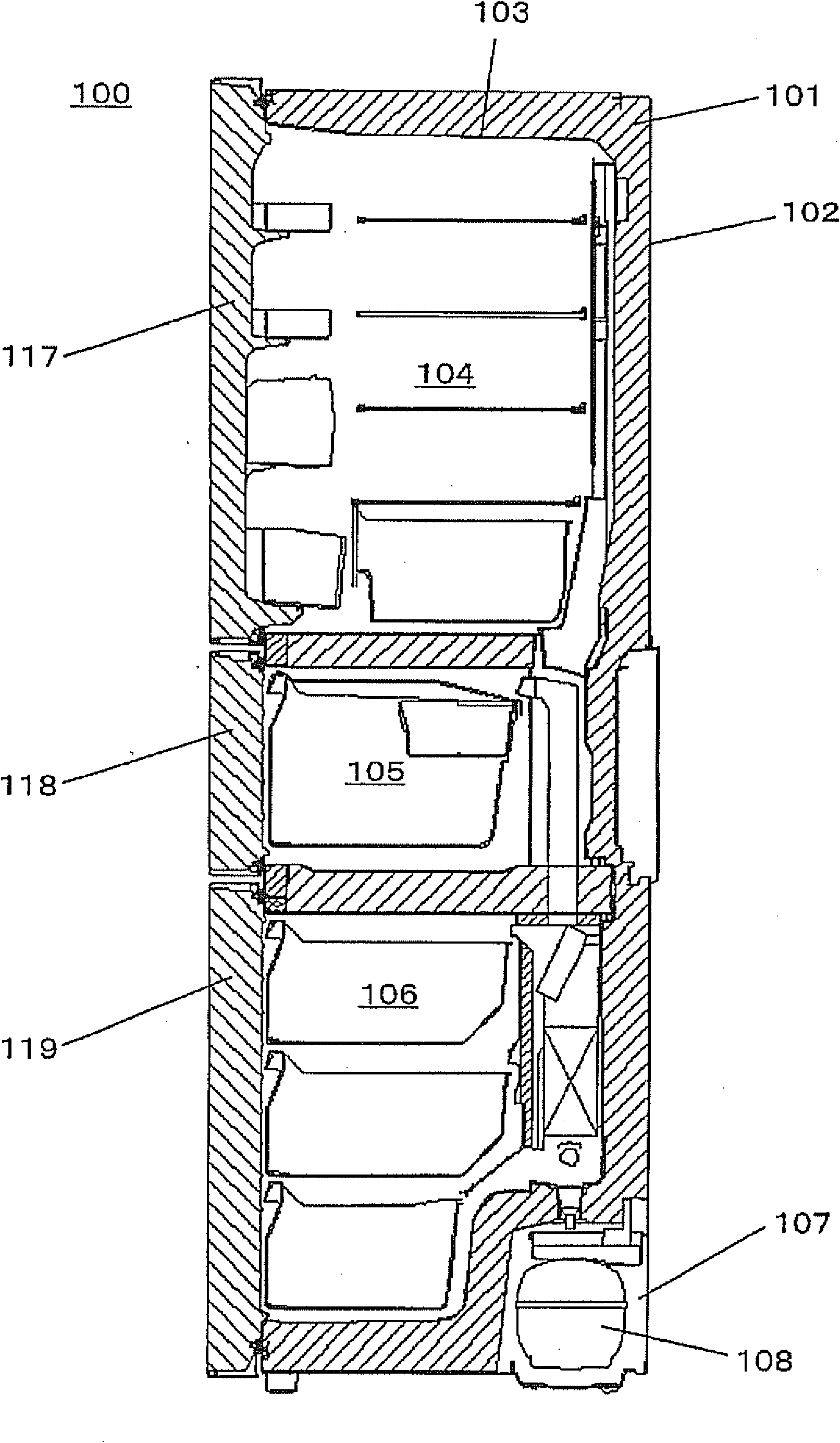
[0066] figure 1 It is a longitudinal sectional view of the refrigerator in Embodiment 1 of this invention.
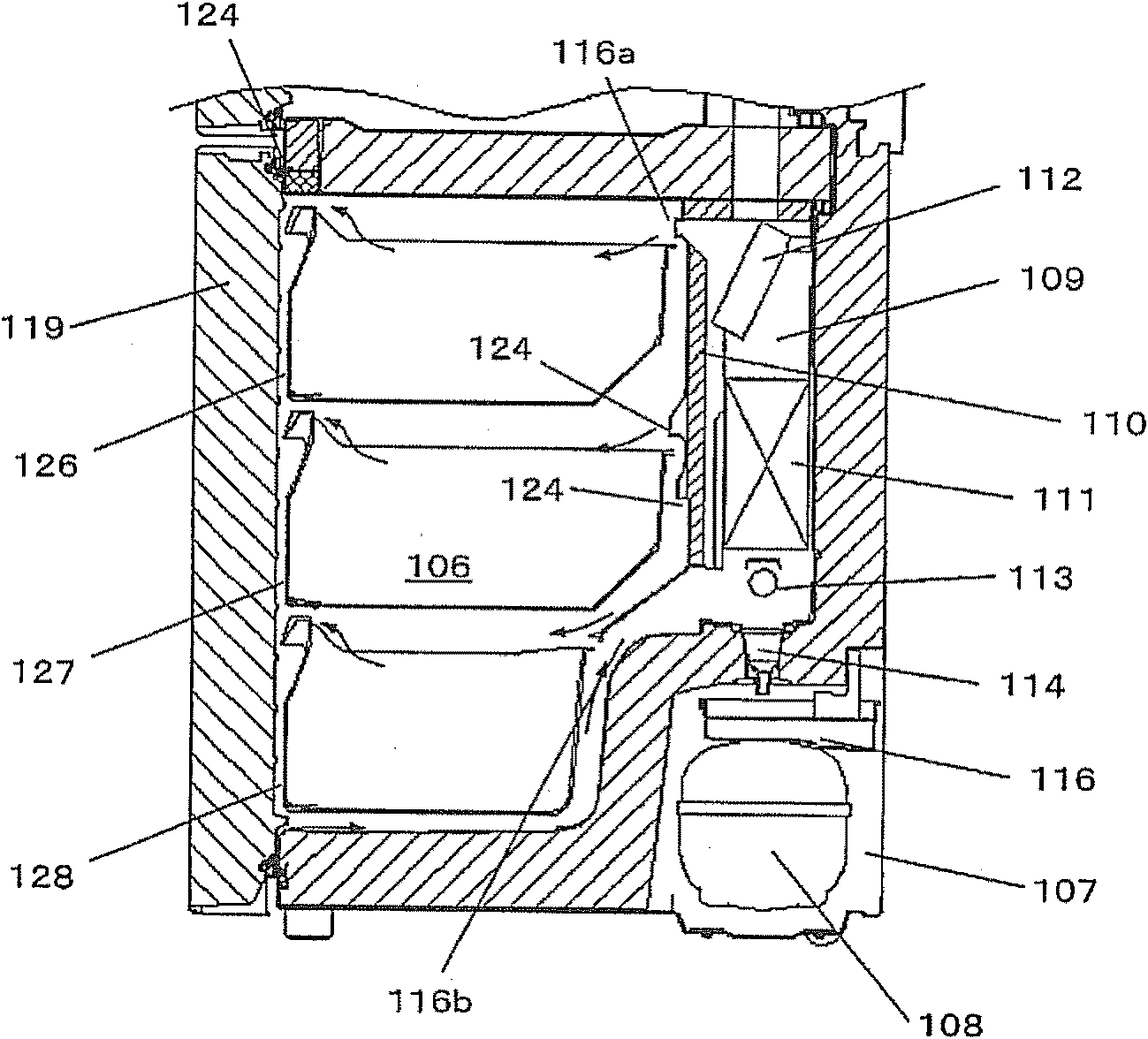
[0067] figure 2 It is a longitudinal sectional view of the freezer compartment of the refrigerator in Embodiment 1 of this invention.
[0068] Figure 3A It is an enlarged sectional view of a main part of the refrigerator according to Embodiment 1 of the present invention.
[0069] Figure 3B It is an enlarged sectional view of a main part of the refrigerator according to Embodiment 1 of the present invention.
[0070] Figure 4 It is a perspective view which shows the divider of the refrigerator in Embodiment 1 of this invention.
[0071] Figure 5 It is an exploded perspective view showing the divider of the refrigerator according to Embodiment 1 of the present invention.
[0072] Image 6 It is a detailed sectional view of the refrigerator according to Embodiment 1 of the present invention.
[0073] Figure 7 It is an exploded perspective view showing th...
Embodiment approach 2
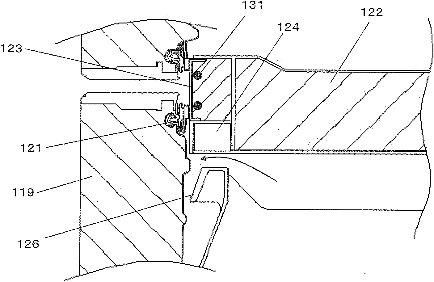
[0110] Figure 10 It is an enlarged cross-sectional view of a main part of the refrigerator according to Embodiment 2 of the present invention.
[0111] In addition, descriptions are omitted for parts that have the same structure or the same technical idea as those of Embodiment 1, but they can be combined and applied as long as there is no problem when this embodiment is implemented in combination with the structure of Embodiment 1. like Figure 10 As shown, the inner surface of the door 119 is provided with a gasket 121 over the entire circumference at the peripheral edge portion (the same applies to the refrigerator compartment 104 and the vegetable compartment 105). Partition body 122 is made of resin and partitions vegetable compartment 105 and freezer compartment 106 up and down. In addition, a metal contact member 123 is provided on the front surface of the divider 122 , and the storage compartment is hermetically sealed by the contact member 123 and the packing 121 b...
Embodiment approach 3
[0119] Figure 11 It is an enlarged cross-sectional view of a main part of the refrigerator according to Embodiment 3 of the present invention.
[0120] In addition, explanations are omitted for parts that have the same structure or the same technical idea as those of Embodiment 1 or 2, but they can be combined and applied as long as there is no problem in implementing this embodiment in combination with the structure of the above embodiment.
[0121] like Figure 11 As shown, refrigerator 100 has gasket 121 over the entire circumference at the inner end of door 119 (the same applies to refrigerator compartment 104 and vegetable compartment 105). Refrigerator 100 has heat insulating partition 150 that partitions vegetable compartment 105 and freezer compartment 106 . The heat insulating partition 150 is integrally formed with the inner box 103 . Storage rooms with different temperature ranges are formed between the heat insulating partition 150 and the door 119 , that is, t...
PUM
 Abstract
Description
Claims
Application Information
 - R&D
- Intellectual Property
- Life Sciences
- Materials
- Tech Scout
- Unparalleled Data Quality
- Higher Quality Content
- 60% Fewer Hallucinations
Browse by: Latest US Patents, China's latest patents, Technical Efficacy Thesaurus, Application Domain, Technology Topic, Popular Technical Reports.
© 2025 PatSnap. All rights reserved.Legal|Privacy policy|Modern Slavery Act Transparency Statement|Sitemap|About US| Contact US: help@patsnap.com


