Connection device for a coil of an electromagnetic switching device

A connection device and electromagnetic switch technology, which is applied to the parts of the connection device, electric switches, contacts, etc., can solve the problems of damage to the surface of the connection point, failure to compensate the dynamic characteristics of the drive unit, etc., and achieve simple geometry, Simplified installation and reduced variance effects

Active Publication Date: 2012-05-23
SIEMENS AG
View PDF9 Cites 1 Cited by
  • Summary
  • Abstract
  • Description
  • Claims
  • Application Information

AI Technical Summary

Problems solved by technology

[0005] The known embodiments of the prior art with respect to the coil connectors of electromagnetic switching devices have the disadvantage that the contact between the drive zone and the coil former is achieved by means of rigid elements (such as pins) which do not provide a positive influence on the dynamic force of the drive unit. characteristics, so switching movements can damage the surface of the connection point

Method used


Image

  • Connection device for a coil of an electromagnetic switching device
  • Connection device for a coil of an electromagnetic switching device
  • Connection device for a coil of an electromagnetic switching device

Examples


Embodiment Construction

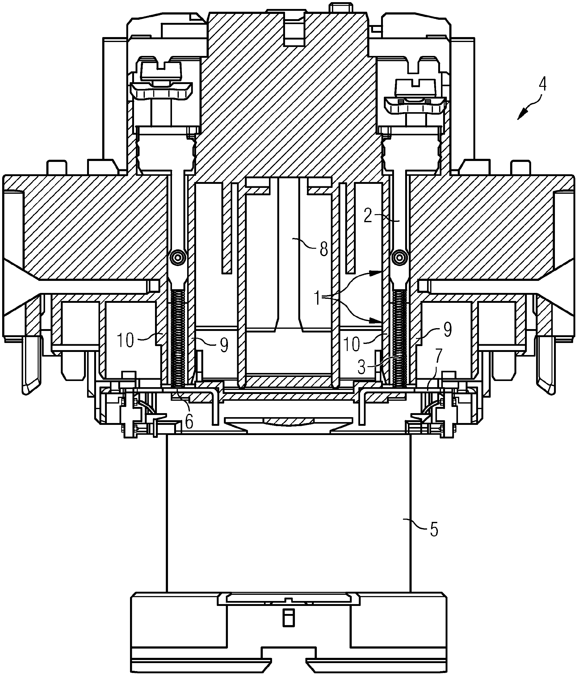
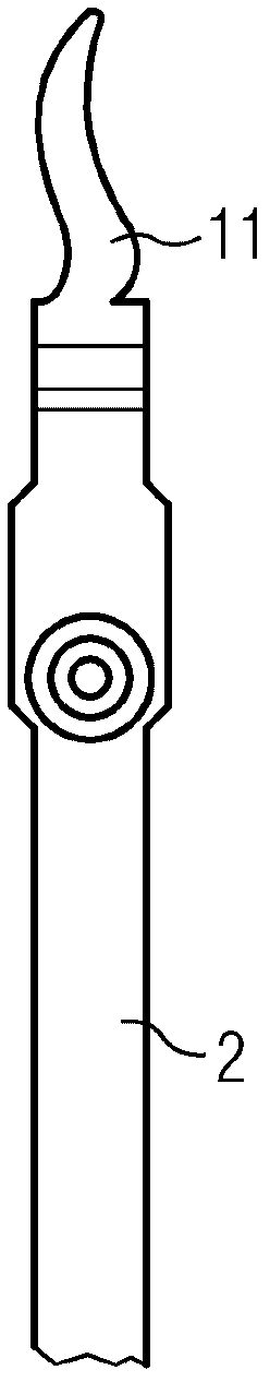
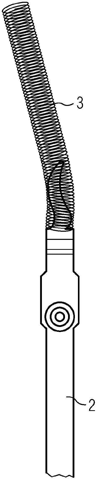
[0015] figure 1 It is the coil connection 1 according to the invention, which is preferably embodied in two parts, with an electrically conductive connection pin 2 and a shape-flexible connection element 3 , which is preferably a compression spring or a leaf spring. The shape-flexible connecting element 3 is plugged onto the conductive connecting pin 2 . This two-part coil connection is arranged in the housing top 4 . A coil 5 is arranged below the top 4 of the housing. The coil 5 has two electrically conductive connecting plates 6 , 7 which can be brought into direct contact with the shape-flexible connecting element 3 . This direct contact is achieved by pressing, since the elastic elements used are stressed, so that a reliable realization of the pressing contact is always ensured. A contact bridge carrier 8 for the contact system of the switching zone is arranged between the coil connectors 1 . The coil connection 1 is mounted between housing guides 9 , 10 whose functio...


PUM


Abstract

The invention relates to a connection device for a coil (5) of an electromagnetic switching device having a switching region comprising contacts and a driving region comprising an anchor, a coil and a yoke, the contacts of the switching region being operatively connected to the driving region. The invention is characterized in that the contacting between the driving region and the coil (5) is established via a form-flexible connection element (3).

Description

technical field [0001] The invention relates to a connection device for a coil of an electromagnetic switching device, comprising a switching area with a plurality of contacts and an actuating area having an armature, a coil and a yoke, wherein , the contacts of the switch area are in operative connection with the drive area. Background technique [0002] A connecting device of the type described above is disclosed from EP 0 394 833 . The connection device includes a connection seat installed on the coil frame and a connection plate, the connection plate includes a conductive plate and has a first end area with a first bend and a second end area with a second bend. The two regions are connected to each other via an intermediate region. Wherein, the first bending part is equipped with a winding pin for connecting the connecting plate and the excitation coil. The second end region includes means for connecting the connection plate and the outer conductor. The first bend is...

Claims


Application Information

Patent Timeline
Patent Type & Authority Applications(China)
IPC IPC(8): H01H1/58H01H50/44H01R13/24
CPCH01H50/443H01R13/2421H01H1/5822
Inventor 彼得·施莱格尔亚历山大·凯因茨罗尔夫·魏因霍尔德
Owner SIEMENS AG
Why Eureka
Try Eureka