
Board-to-board-type connector

A board-to-board connector and connector technology, which is applied in the direction of connection, fixed connection, and parts of the connection device, can solve the problems of reduced contact degree, inability to maintain male and female terminals, and reduced elasticity, so as to improve the contact degree Effect

Inactive Publication Date: 2012-05-23
HUMAN ELECTRONICS
View PDF8 Cites 5 Cited by
  • Summary
  • Abstract
  • Description
  • Claims
  • Application Information

AI Technical Summary

Problems solved by technology

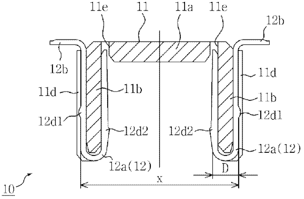
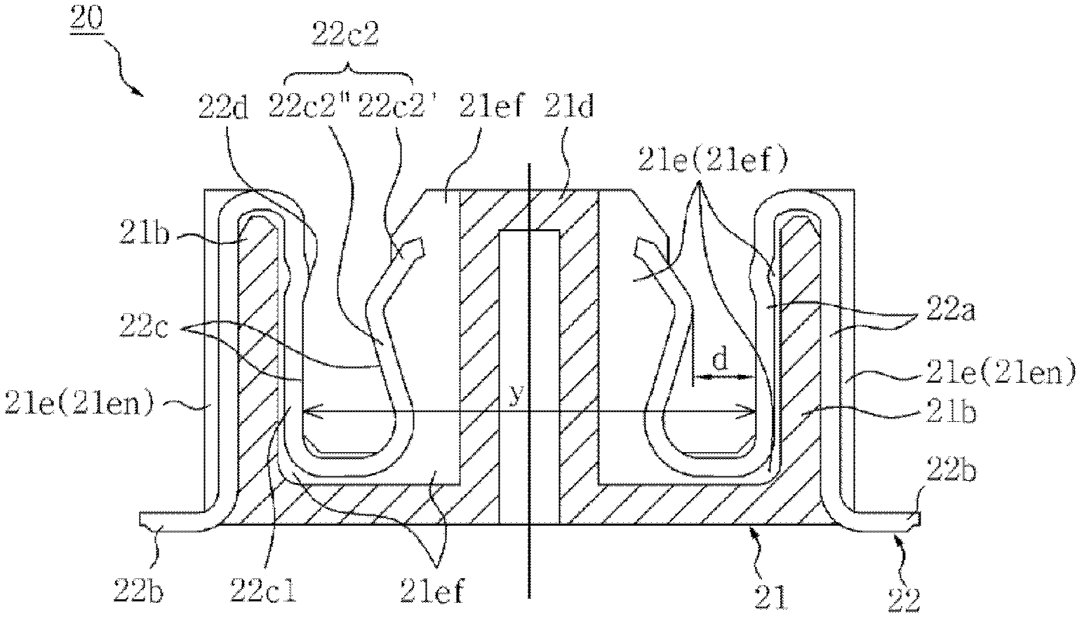
[0008] When the board-to-board connector of the above prior art is applied, one side (22c2) of the female terminal (22) will elastically change to form an electrical contact point with the male terminal (12), so the above-mentioned male and female terminals (12, 22) It is easy to combine with a little force, on the contrary, this means that a little impact between the male and female terminals (12, 22) is easy to separate
[0009] Moreover, since the stress caused by the installation / disengagement between the above-mentioned male and female terminals (12, 22) is only concentrated on one side (22c2) of the above-mentioned female terminal (22), when the above-mentioned board-to-board connector is used for a long time, The elasticity of the above-mentioned deformed part will be reduced, and as a result, a stable electrical contact point between the male and female terminals (12, 22) cannot be maintained
[0010] And, when applying the board-to-board connector of the above-mentioned prior art, one side (22c2) of the above-mentioned female terminal is asymmetrically formed on the protrusion (12d1, 12d2) of the male terminal (12) and formed on one side of the female terminal. The projections (22d) of the male and female terminals (12, 22) can be combined only when they are deformed, so the degree of contact will be reduced
[0011] Therefore, the user cannot determine whether the above-mentioned male and female terminals (12, 22) are normally connected or not. failure, and damage to the product

Method used


Image

  • Board-to-board-type connector
  • Board-to-board-type connector
  • Board-to-board-type connector

Examples


Embodiment Construction

[0049] The board-to-board connector according to the present invention will be described in more detail through the following application examples on the basis of the attached drawings.

[0050] The present invention can be applied to representative ultra-miniature small-pitch board-to-board connectors.

[0051] 1st embodiment

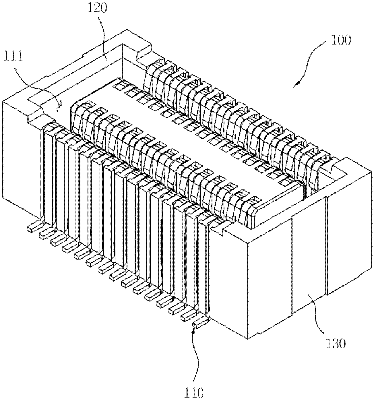
[0052] image 3 , Figure 4 According to the first embodiment of the present invention, the oblique view of the connector female seat (100) and the connector male seat (200) constituting the board-to-board connector is shown, Figure 5 It is a perspective view of the combination state between the above-mentioned connector female seat (100) and the connector male seat (200).

[0053] Such as image 3 , Figure 5 As shown, the board-to-board connector of the present invention is composed of a connector female seat (100) combined with a plurality of female terminals (110), and a connector male seat (200) combined with a plurality of male terminals (2...


PUM


Abstract

A patient worn medical monitoring device (10) includes a multi-channel electrical connector (18) for connecting a lead set (22) to a monitoring unit (16) is able to wirelessly transmit a patient's physiological data over a telemetric link to a receiver unit for remote monitoring purposes. The multi-channel electrical connector includes first and second connector elements (40,42) disposed on either one of the monitoring unit or lead set. The first connector element includes a plurality of rigid pins (44) disposed between a plurality of ribs (50). The second connector element includes a compressible substrate carrying flexible electrically conductive pads (46) that flex independently of one another. The connector elements to are configured to such that the pins of the first connector element electrically engage the flexible electrically conductive pads of the second connector element.

Description

technical field [0001] The invention relates to a board-to-board connector, specifically disclosing a kind of blocking protrusions on both sides of the male and female terminals forming electrical contact points to improve the bonding force between the above-mentioned male and female terminals, and to improve the above-mentioned male and female terminals The acting stress is distributed to both sides, so when the board-to-board connector is used for a long time, it is a board-to-board connector that can maintain a stable contact state between male and female terminals. Background technique [0002] Generally speaking, the electrical connector used in the electrical and electronic industries is a means of connecting more than two electrical or electronic accessories. According to the development of the electrical and electronic industries, its frequency of use has also greatly increased. In particular, it is difficult to produce two This kind of connector is more needed when ...

Claims


Application Information

Patent Timeline
Patent Type & Authority Applications(China)
IPC IPC(8): H01R12/62H01R12/71
CPCH01R12/716H01R13/2492H01R13/20
Inventor 崔润植曺永烈
Owner HUMAN ELECTRONICS
Learn More