Driver for cooperating with a wall dimmer

一种驱动器、调光的技术,应用在驱动器领域

Inactive Publication Date: 2012-05-23
SIGNIFY HLDG BV
View PDF3 Cites 0 Cited by
  • Summary
  • Abstract
  • Description
  • Claims
  • Application Information

AI Technical Summary

Problems solved by technology

However, there are situations where it is desirable to be able to dim a lamp with a mains dimmer

Method used


Image

  • Driver for cooperating with a wall dimmer
  • Driver for cooperating with a wall dimmer
  • Driver for cooperating with a wall dimmer

Examples


Embodiment Construction

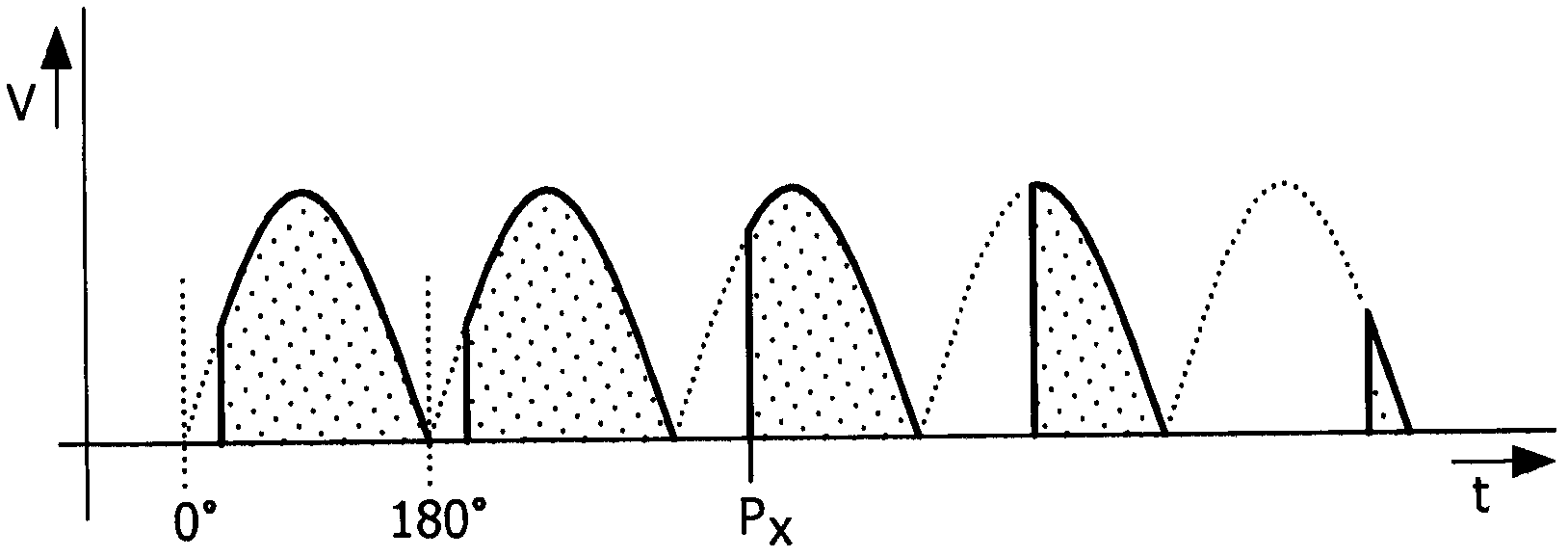
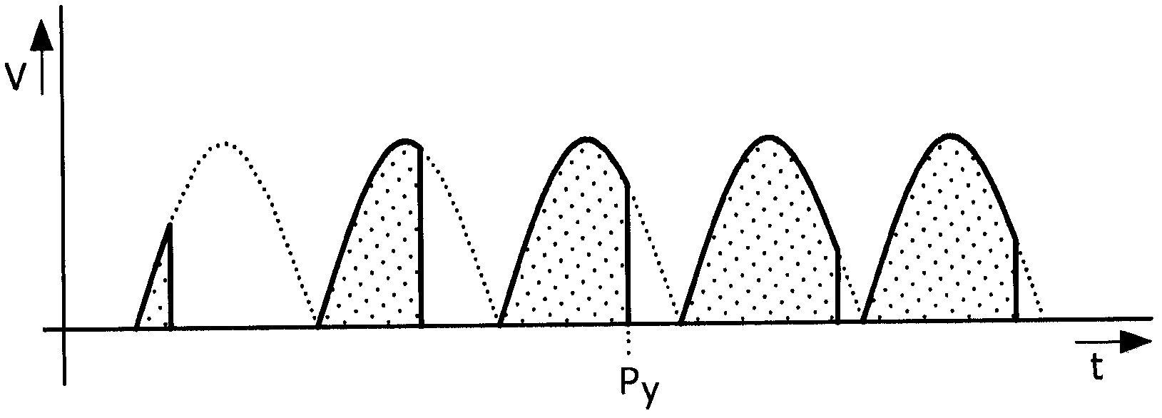
[0018] image 3 is a block diagram schematically illustrating one embodiment of an electronic driver 100 according to the present invention. The driver 100 has an input 101 for receiving phase cut mains U1 from a mains dimmer (not shown) and an output 109 for connection to a lamp L. FIG.

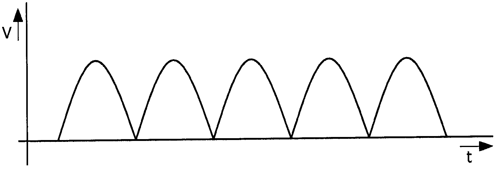
[0019] The rectifier 110 has an input 111 connected to the driver input 101 and has an output 119 for providing rectified mains U2. The rectifier 110 can be implemented, for example, as a diode bridge. It should be noted that rectified mains U2 has essentially the same waveform as mains U1, with the difference that the polarity of all current half-cycles is now the same. Since rectifiers are well known to those skilled in the art, a more detailed discussion of the design or operation of rectifier 110 need not be discussed here.

[0020] The DC / DC converter 120 has an input 121 connected to the rectifier output 119 and has an output 129 for providing a substantially constant output voltage...


PUM


Abstract

A driver (100; 200) for driving a dimmable load (L) is powered from phase- cut mains (U1) and determines the dimming state of the load on the basis of the phase of the cutting of the mains. The driver comprises: a load current generating device (130; 230) generating load current; a controllable auxiliary load (170; 270) connected to an input (131; 231) of the load current generating device; a control device (140; 240) controlling the auxiliary load. The control device has an input (141; 241) receiving a signal indicating the momentary voltage at the driver input. The load current generating device generates interrupted current pulses, so that the average output current corresponds to the dim command reflected by the phase cutting angle of the input mains. The control device switches the auxiliary load on during those time periods when the output current generated by the load current generating device is zero.

Description

technical field [0001] The invention particularly relates to a driver for driving light sources, in particular LEDs, but the driver of the invention may also be used for driving any type of load. Background technique [0002] In traditional lighting applications, incandescent lamps based on resistive heating of the light-emitting element are used. The lights are powered by mains electricity, which in Europe involves 230V AC at 50Hz. Traditionally, such lamps are connected in series with an on / off switch so that the lamp is either off or produces light at nominal power. To meet the need to be able to dim lights (i.e. reduce light levels), mains dimmers have been developed as devices connected in series with the lights, either as stand-alone devices or connected to the wall The installed switches are integrated. Such dimmers generally operate based on phase-cutting the mains voltage with TRIACs (triacs). Since such dimmers are well known, the following description will be ...

Claims


Application Information

Patent Timeline
Patent Type & Authority Applications(China)
IPC IPC(8): H05B33/08H05B44/00
CPCH05B33/0815H05B33/0809H05B45/37H05B47/10H05B45/31Y02B20/30
Inventor R·W·C·范德文肯H·M·J·M·卡尔曼
Owner SIGNIFY HLDG BV
Why Eureka
Try Eureka