Dynamic decorative clock

A clock and dynamic technology, applied in the field of dynamic decorative clocks, can solve the problems of small overall area and limited decorative effect, and achieve the effect of ensuring timing accuracy and outstanding decorative effect.

Inactive Publication Date: 2017-10-13
BAOJI UNIV OF ARTS & SCI
View PDF8 Cites 0 Cited by
  • Summary
  • Abstract
  • Description
  • Claims
  • Application Information

AI Technical Summary

Problems solved by technology

Existing decorative clock patent situation is as follows: Seat (outdoor leisure type), the Chinese patent of authorized announcement number CN302473144S, belongs to appearance design patent, is the chair clock of landscape decoration type; The Chinese patent of authorized announcement number CN303018509S belongs to appearance design The patent mainly lies in the shape and pattern; the decorative clock with the authorized announcement number CN201853078U belongs to the utility model patent, and is mainly a decorative clock with a rotating decorative turntable; there are also record-shaped clocks, bicycle-style decorative clocks, dynamic landscape decorative clocks, and big red Design patents and utility model patents for craft wall clocks, etc., have made some innovations to the appearance of the clock, but the internal structure of the actual clock has not changed, and, because the overall area is small, the decorative effect is limited; there are also clocks. Invention patents are all local changes and designs to the local structure of the clock. The structural features are similar, but they are still limited to the traditional watch model.

Method used


Image

  • Dynamic decorative clock
  • Dynamic decorative clock
  • Dynamic decorative clock

Examples


Embodiment Construction

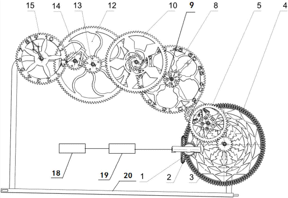
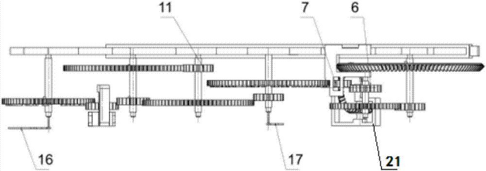
[0012] The present invention will be described in detail below in conjunction with the accompanying drawings and specific embodiments.

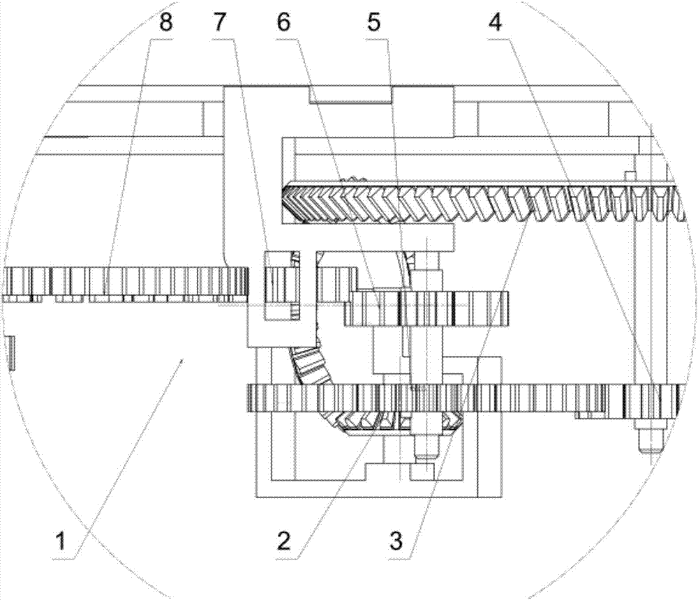
[0013] A dynamic decorative clock, see figure 1 and figure 2 , with clock generator 18, driving stepper motor 19, hour hand 16, minute hand 17, frame 20, auxiliary support 21 and transmission system, described transmission system is to expand into single-layer plane or project on the plane and not overlap each other The space structure has changed people's traditional understanding of clocks and watches. The clock generator 18 is electrically connected to the drive stepper motor 19. The clock generator 18 is connected to an external power supply, and the clock generator 18 realizes time control and drives the stepper motor Enter the motor 19 to realize the motion input of the rear transmission system; all transmission systems are connected to the frame 20, or connected to the frame 20 through the auxiliary bracket 21, the third bevel gear 3...


PUM


Abstract

The invention discloses a dynamic decorative clock. The dynamic decorative clock is provided with a clock generator, a driving stepping motor, an hour pointer, a minute hand, a rack, an auxiliary support and a drive system. The drive system is fixed to the rack through the auxiliary support. The drive system is provided with a first bevel gear, a second bevel gear, a third bevel gear, a first cylindrical gear, a second cylindrical gear, a third cylindrical gear, a fourth cylindrical gear, a fifth cylindrical gear, a sixth cylindrical gear, a seventh cylindrical gear, an eighth cylindrical gear, a ninth cylindrical gear, a tenth cylindrical gear, an eleventh cylindrical gear and a twelfth cylindrical gear. The structure of a traditional lamellar overlapped drive system of a clock is unfolded into a double-layer plane or a space stereoscopic structure, the projection of which on a plane is not overlapped, the drive system of the clock can be clearly displayed, accurate running of the minute hand and the hour pointer is guaranteed, the timing accuracy of the clock is guaranteed, and the drive beauty of a dynamic mechanical system can be shown.

Description

technical field [0001] The invention belongs to the technical field of decorative clocks, in particular to a dynamic decorative clock. Background technique [0002] In modern society, when it comes to clocks and watches, people will think of watches, but various other types of clocks such as table clocks, wall clocks, and grandfather clocks are declining. Existing decorative clock patent situation is as follows: Seat (outdoor leisure type), the Chinese patent of authorized announcement number CN302473144S, belongs to appearance design patent, is the chair clock of landscape decoration type; The Chinese patent of authorized announcement number CN303018509S belongs to appearance design The patent mainly lies in the shape and pattern; the decorative clock with the authorized announcement number CN201853078U belongs to the utility model patent, and is mainly a decorative clock with a rotating decorative turntable; there are also record-shaped clocks, bicycle-style decorative clo...

Claims


Application Information

Patent Timeline
Patent Type & Authority Applications(China)
IPC IPC(8): G04C3/14G04B13/02
CPCG04B13/02G04C3/14
Inventor 王娟平
Owner BAOJI UNIV OF ARTS & SCI
Why Eureka
Try Eureka