RTC clock calibration method and industrial field calibration device
A clock calibration and industrial site technology, applied to clocks, electronic timers, and time indications, etc., can solve complex changes in the on-site working environment, increase calibration costs and complexity, and are not suitable for external standard clocks and on-site instrument calibration Problems such as carrying the device with you
- Summary
- Abstract
- Description
- Claims
- Application Information
AI Technical Summary
Problems solved by technology
Method used
Image
Examples
Embodiment 1
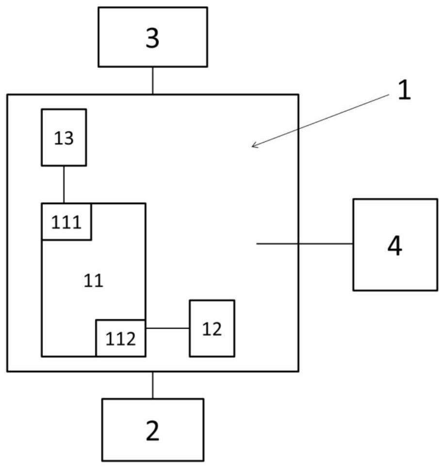
[0055] In this embodiment, a pressure (instrument) calibrating device used for calibrating or calibrating a pressure instrument in an industrial field is taken as an example to illustrate the RTC clock calibration process of the calibrating device in an industrial field. figure 1 The basic composition of a typical pressure calibration device is shown: the pressure calibration device includes an MCU main board 1, a pressure acquisition module 2, an electrical signal measurement module 3 and a battery module 4, and the pressure acquisition module and the electrical signal measurement module 3 are respectively connected to the MCU main board 1 is electrically connected, and the battery module 4 is electrically connected to the MCU main board 1 for supplying power to each module.
[0056] Wherein, MCU motherboard 1 is provided with processing unit (i.e. CPU) 11, high frequency crystal oscillator (hereinafter referred to as HSE) 12 and low frequency crystal oscillator (LSE) 13, is p...
Embodiment 2
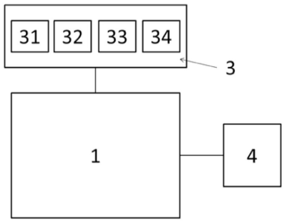
[0074] In this embodiment, a process (instrument) verification device for verifying or calibrating a process instrument in an industrial field is taken as an example to illustrate the RTC clock calibration process of the industrial field verification device. figure 2 The basic composition of a typical process verification device is shown: the process verification device includes an MCU main board 1, an electrical signal measurement module 3 and a battery module 4, further, the electrical signal measurement module 3 includes a current measurement unit 31, a voltage measurement unit 32, The resistance measurement unit 33 and the temperature measurement unit 34, the temperature measurement unit 34 includes a temperature sensor, which can measure the ambient temperature of the electrical signal measurement module 3 as the cold junction temperature when the thermocouple process signal is calibrated.
[0075] The difference from the pressure calibration device in Embodiment 1 is tha...
Embodiment 3
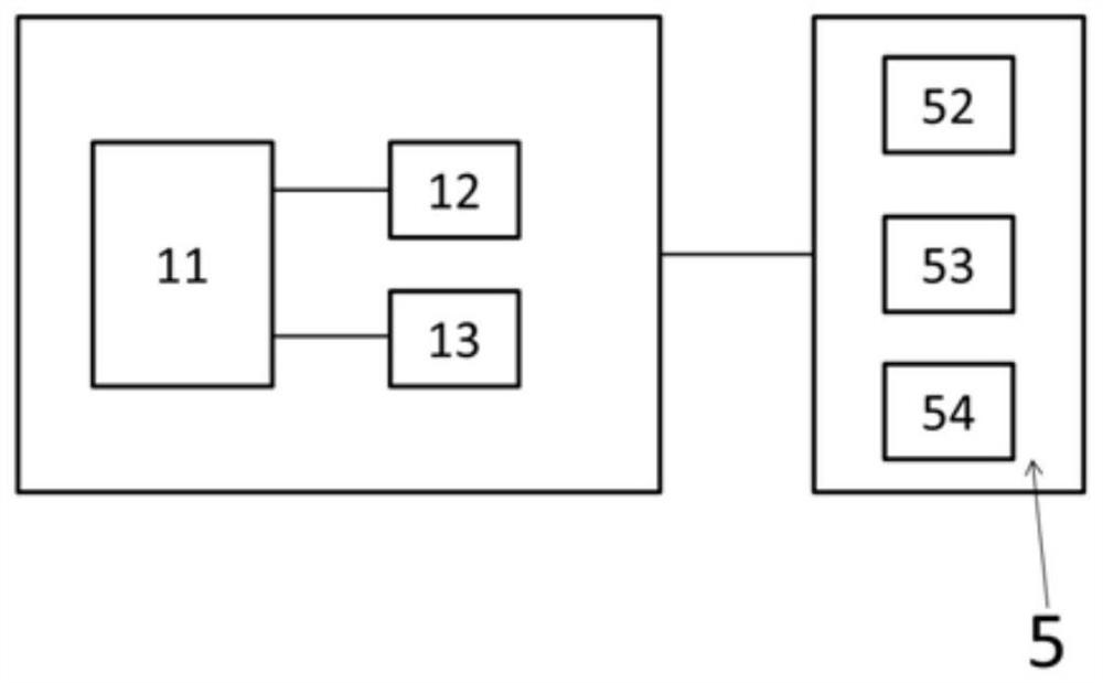
[0085] In this embodiment, a temperature (instrument) verification device used for verifying or calibrating a temperature instrument in an industrial field is taken as an example to illustrate the RTC clock calibration process of the industrial field verification device. image 3 The basic composition of a typical temperature calibration device is shown: in this embodiment, the temperature calibration device includes an MCU main board 1 and a temperature acquisition module 5 electrically connected to the MCU main board 1, wherein:
[0086] MCU motherboard 1 includes a processing unit (CPU) 11 and a clock module formed by high-frequency crystal oscillator (HSE) 12 and low-frequency crystal oscillator (LSE) 13, HSE is used as the system clock signal source of MCU motherboard 1, and also as a high-frequency calibration of LSE Clock signal, preferably, when HSE is used as a high-frequency calibration signal of LSE, frequency multiplication technology is used to increase its frequen...
PUM
 Abstract
Description
Claims
Application Information
 - R&D
- Intellectual Property
- Life Sciences
- Materials
- Tech Scout
- Unparalleled Data Quality
- Higher Quality Content
- 60% Fewer Hallucinations
Browse by: Latest US Patents, China's latest patents, Technical Efficacy Thesaurus, Application Domain, Technology Topic, Popular Technical Reports.
© 2025 PatSnap. All rights reserved.Legal|Privacy policy|Modern Slavery Act Transparency Statement|Sitemap|About US| Contact US: help@patsnap.com


