Timing calibration method of internal clock source of chip and related device

A technology of internal clock and calibration method, which is applied in the direction of automatic power control and electrical components, etc., can solve the problems of calibration clock source without temperature compensation, low precision of low-speed oscillator, large timing calibration error, etc., to achieve precise timing accuracy and improve The effect of calibration accuracy and simple method

Pending Publication Date: 2021-04-30
GREE ELECTRIC APPLIANCES INC
View PDF1 Cites 0 Cited by
  • Summary
  • Abstract
  • Description
  • Claims
  • Application Information

AI Technical Summary

Problems solved by technology

When the chip enters the low-power mode, only the low-speed oscillator can run for timekeeping. Due to the low precision of the low-speed oscillator, the calibration error of the timing by the low-speed oscillator in the prior art is relatively large
Chinese patent application CN110308762A patent discloses a cali

Method used


Image

  • Timing calibration method of internal clock source of chip and related device
  • Timing calibration method of internal clock source of chip and related device
  • Timing calibration method of internal clock source of chip and related device

Examples


Embodiment Construction

[0043] The following will clearly and completely describe the technical solutions in the embodiments of the present invention with reference to the accompanying drawings in the embodiments of the present invention. Obviously, the described embodiments are only some, not all, embodiments of the present invention. Based on the embodiments of the present invention, all other embodiments obtained by persons of ordinary skill in the art without creative efforts fall within the protection scope of the present invention.

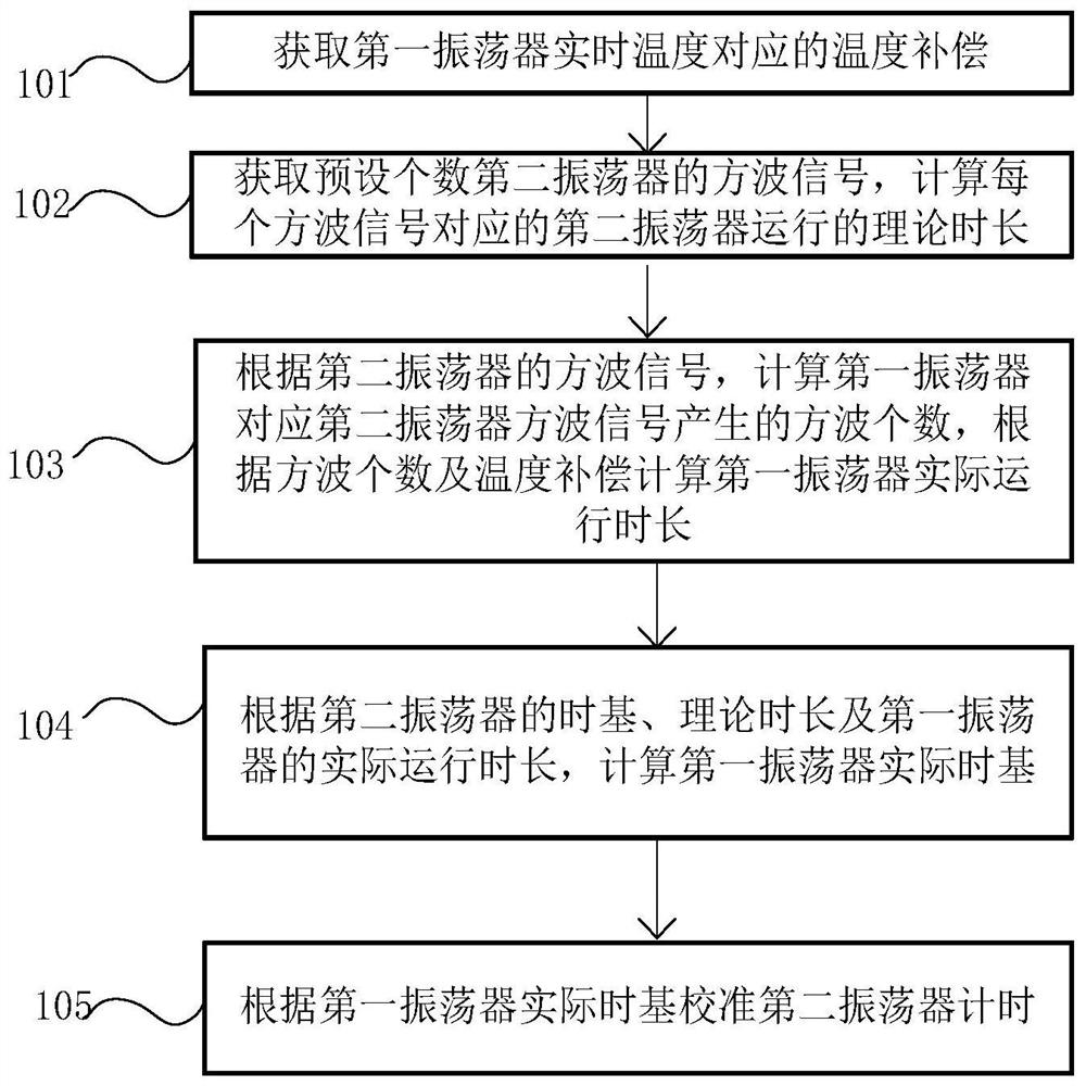
[0044] figure 1 It is a schematic diagram of the timing calibration method of the internal clock source of the chip provided by the embodiment of the present invention, and the method includes:

[0045] S101. Acquire temperature compensation corresponding to the real-time temperature of the first oscillator.

[0046] In the present invention, the temperature compensation corresponding to the real-time temperature of the first oscillator can be obtained by taking t...


PUM


Abstract

The invention discloses a timing calibration method for a clock source in a chip and a related device, and the method comprises the steps: obtaining the temperature compensation corresponding to the real-time temperature of a first oscillator, so as to improve the calibration precision of the first oscillator; obtaining square wave signals of a preset number of second oscillators, and calculating the theoretical operation duration of the second oscillator corresponding to each square wave signal; calculating the number of square waves generated by the first oscillator corresponding to the square wave signal of the second oscillator according to the square wave signal of the second oscillator, and calculating the actual operation duration of the first oscillator according to the number of square waves and temperature compensation; calculating the actual time base of the first oscillator according to the time base of the second oscillator, the theoretical time length and the actual operation time length of the first oscillator; and calibrating the timing of the second oscillator according to the actual time base of the first oscillator. The method is simple, and the timing precision of the second oscillator is adjusted to be consistent with the precision of the first oscillator, so that the timing precision of the second oscillator is ensured to be accurate.

Description

technical field [0001] The invention relates to the field of clock calibration, in particular to the field of chip internal clock timing calibration, in particular to a timing calibration method and related devices for chip internal clock sources. Background technique [0002] In chip design, in order to reduce chip cost, crystal-free vibration has gradually become a design trend for low-end chips. In chip casting, a multi-project wafer (Multi Project Wafer, referred to as MPW) designs multiple integrated circuits with the same process on the same wafer, and obtains a variety of chip samples. This kind of MPW chip can greatly reduce the cost of integrated circuit research and development, but because it has not gone through the formal CP mass production calibration process, the chip has not gone through the system parameter test and hardware configuration process after the chip is produced and processed in the factory, and the clock frequency of the internal clock source of ...

Claims


Application Information

Patent Timeline
IPC IPC(8): H03L7/099H03L7/18
CPCH03L7/0992H03L7/18
Inventor 梁炯辉谢容郑良剑李秀菲伍衍亮周婷
Owner GREE ELECTRIC APPLIANCES INC
Why Eureka
Try Eureka