Plate heat exchanger plate transferring system and transferring method thereof

A plate heat exchanger and plate technology, which is applied in the direction of transportation and packaging, conveyors, conveyor objects, etc., can solve the problems of low efficiency, laborious plate transfer, etc., and achieve the effect of easy adjustment and convenient stacking and collection

Pending Publication Date: 2022-02-08
ANHUI PROPELLENT HEAT TRANSFER TECH CO LTD
View PDF17 Cites 0 Cited by
  • Summary
  • Abstract
  • Description
  • Claims
  • Application Information

AI Technical Summary

Problems solved by technology

[0005] During the drilling process of the plates of the heat exchanger, the plates to be processed need to be manually transferred to the processing equipment for drilling processing. After the processing is completed, they will be stacked and collected manually to facilitate subsequent processing. Processing, this kind of plate transfer is laborious and inefficient

Method used


Image

  • Plate heat exchanger plate transferring system and transferring method thereof
  • Plate heat exchanger plate transferring system and transferring method thereof
  • Plate heat exchanger plate transferring system and transferring method thereof

Examples


Embodiment 1

[0040] as attached Figure 1-3 As shown, the present invention provides a kind of technical scheme:

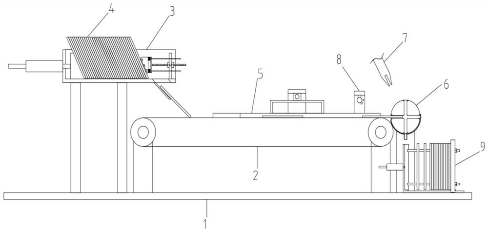
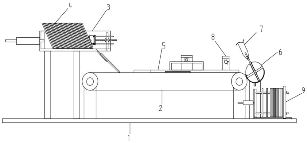
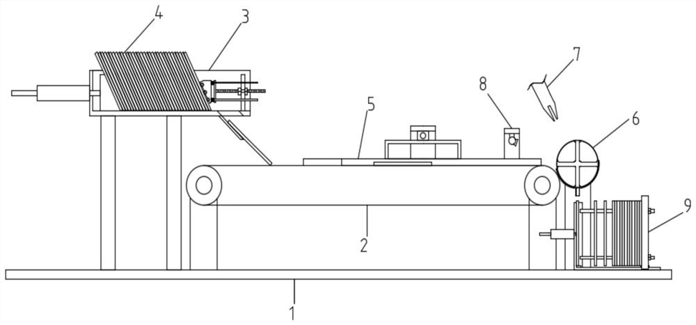
[0041]A plate transfer system for a plate heat exchanger, comprising a bottom plate 1, a conveyor belt 2 is provided in the middle of the top of the bottom plate 1, a storage and unloading mechanism 3 is provided on the input side of the conveyor belt 2, and a plate 4 is loaded in the storage and unloading mechanism 3 , the top of the conveyor belt 2 is provided with a plate guide mechanism 5, the output side of the conveyor belt 2 is provided with a plate turning and unloading mechanism 6, and the upper side of the plate turning and unloading mechanism 6 is provided with a clamping mechanical arm 7. The mechanical arm 7 is used to transfer the plate 4 to the processing equipment, and after the processing is completed, the plate 4 is sent back to the plate turning and unloading mechanism 6. The lower side of the plate turning and unloading mechanism 6 is provided with The fin...

Embodiment 2

[0047] Based on Embodiment 1, this embodiment specifically introduces a structural design of a storage and unloading mechanism:

[0048] as attached Figure 4 As shown, the storage and unloading mechanism 3 includes an outer casing 31, the top and the right end of the outer casing 31 are openings, and an inclined push block 32 is movable in the outer casing 31, and a first electric push rod 33 is installed on the left end of the outer casing 31. The output rod of the first electric push rod 33 runs through the outer shell 31 and is fixedly connected with the left end of the inclined push block 32. The bottom right side of the outer shell 31 is provided with a discharge port 34, and the bottom left end of the discharge port 34 is provided with a discharge port. A partition 37 is arranged on the right side of the top of the plate 35 and the discharge opening 34, and a plate anti-slip mechanism 38 is installed on the left side of the partition 37.

[0049] When the above-mention...

Embodiment 3

[0053] Based on Embodiment 2, this embodiment specifically introduces the structural design of a plate anti-slip mechanism:

[0054] as attached Figure 5 As shown, the plate anti-slip mechanism 38 includes a mounting plate 381, the middle part of the right end of the mounting plate 381 is fixedly connected with an adjusting screw 382, ​​the adjusting screw 382 moves through the partition 37, and the adjusting screw 382 is provided with two sets of adjusting nuts 383, the two sets of adjusting nuts 383 is located on the left and right sides of the partition 37, and the left side of the mounting plate 381 is provided with a slanting block 385, and the right end of the slanting block 385 is fixedly connected with two sets of upper and lower limit rods 384, and the right ends of the limit rods 384 move through the mounting plate in turn. 381 and the partition 37 , a buffer spring 386 is connected between the inclined block 385 and the mounting plate 381 , and the buffer spring 38...


PUM


Abstract

The invention relates to the technical field of heat exchanger plate machining, in particular to a plate heat exchanger plate transferring system which comprises a bottom plate. A conveying belt is arranged in the middle of the top end of the bottom plate, a storage and unloading mechanism is arranged at the input side of the conveying belt, and plates are loaded in the storage and unloading mechanism. According to the storage and unloading mechanism designed by the invention, more to-be-processed plates can be pre-stored at one time, and the single-plate unloading process from the plates to the conveyor belt can be realized, so that the plates are orderly discharged, and the accurate operation in the whole transferring process is facilitated; a designed plate overturning and discharging mechanism can overturn and tilt the plates, and then a clamping mechanical arm can conveniently transfer the plate to a machining device for drilling treatment; after machining is finished, the plate overturning and discharging mechanism can rotate the finished plates to a vertical angle to be guided out, and therefore the loading of a subsequent finished product loading mechanism is facilitated; and the designed finished product loading mechanism is used for loading, and the plates can be automatically gathered and collected on a collecting rod, so that the plates can be conveniently stacked and collected.

Description

technical field [0001] The invention relates to the technical field of heat exchanger plate processing, in particular to a plate heat exchanger plate transfer system and a transfer method thereof. Background technique [0002] A heat exchanger is a device that transfers part of the heat of a hot fluid to a cold fluid, also known as a heat exchanger. It is an energy-saving device that transfers heat between materials between two or more fluids at different temperatures. It transfers heat from a fluid with a higher temperature to a fluid with a lower temperature, so that the fluid temperature reaches the index specified in the process to meet the needs of the process conditions, and it is also one of the main equipment to improve energy utilization. Heat exchangers play an important role in chemical, petroleum, power, food and many other industrial productions. In chemical production, heat exchangers can be used as heaters, coolers, condensers, evaporators and reboilers, etc.,...

Claims


Application Information

Patent Timeline
Patent Type & Authority Applications(China)
IPC IPC(8): B65G47/06B65G47/24B65G47/34B65G47/84B65G47/90
CPCB65G47/06B65G47/24B65G47/34B65G47/846B65G47/90B65G2201/022B65G2203/041
Inventor 胡西芹刘红军张凌霞张志峰
Owner ANHUI PROPELLENT HEAT TRANSFER TECH CO LTD
Why Eureka
Try Eureka