Tire rubber index calculating method, device, and program
A calculation method and tire technology, applied in the rubber index calculation program, rubber index calculation device, rubber index calculation field of rubber index, can solve the problems of high manufacturing precision, unrealistic, long time measurement, etc.
- Summary
- Abstract
- Description
- Claims
- Application Information
AI Technical Summary
Benefits of technology
Problems solved by technology
Method used
Image

Examples
no. 1 Embodiment approach
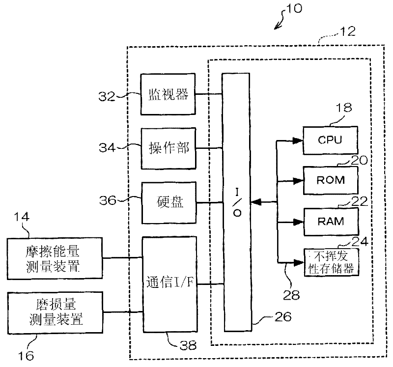
[0037] exist figure 1 A tire rubber index calculation system 10 according to the present embodiment is shown in FIG. As shown in the figure, a tire rubber index calculation system 10 includes a tire rubber index calculation device 12 , a friction energy measurement device 14 , and a wear amount measurement device 16 .
[0038] Such as figure 1 As shown, the tire rubber index calculation device 12 is composed of a computer 30, and the computer 30 is connected to a CPU (Central Processing Unit) 18, a ROM (Read Only Memory) 20, a RAM (Random Access Memory) 22, and a bus 28 respectively. A volatile memory 24 and an input / output interface (I / O) 26 .
[0039] A monitor 32 including a liquid crystal display or the like, an operation unit 34 including a keyboard, a mouse, or the like, a hard disk 36 , and a communication interface (I / F) 38 are connected to the I / O 26 . The friction energy measuring device 14 and the wear amount measuring device 16 are connected to the communicati...
no. 2 Embodiment approach
[0063] Next, a second embodiment of the present invention will be described. In addition, the same code|symbol is attached|subjected to the same part as 1st Embodiment, and the detailed description is abbreviate|omitted.
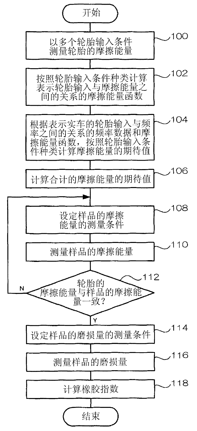
[0064] In the first embodiment, the friction energy function is obtained for each type of tire input condition, and the expected value of the total tire friction energy is obtained, and then the rubber index is calculated. However, in this embodiment, the description is given for each tire input condition A case where the rubber index is calculated and the expected value of the rubber index is calculated from the rubber index.
[0065] Since the rubber index calculation device of this embodiment is the same as that of the first embodiment, description thereof will be omitted.
[0066] Next, refer to Figure 4 The shown flowchart illustrates the processing performed by the CPU 18 of the rubber index calculation device 12 for tires. in addition, Figure 4 ...
no. 3 Embodiment approach
[0084] Next, a third embodiment of the present invention will be described. In addition, the same code|symbol is attached|subjected to the same part as 1st Embodiment, and the detailed description is abbreviate|omitted.
[0085] In the first embodiment, the frictional energy of the sample was measured by the frictional energy measuring device 14, but in this embodiment, the finite element method (FEM) is described using a sample model obtained by dividing the sample into a plurality of components. Simulations were performed to determine the frictional energy profile of the contact surface of the sample.
[0086] In addition, since the rubber index calculation apparatus of this embodiment is the same as that of 1st Embodiment, description is abbreviate|omitted.
[0087] Next, refer to Figure 5 The shown flowchart illustrates the processing performed by the CPU 18 of the rubber index calculation device 12 for tires. in addition, Figure 5 The programs of the shown processin...
PUM
 Abstract
Description
Claims
Application Information
 - R&D
- Intellectual Property
- Life Sciences
- Materials
- Tech Scout
- Unparalleled Data Quality
- Higher Quality Content
- 60% Fewer Hallucinations
Browse by: Latest US Patents, China's latest patents, Technical Efficacy Thesaurus, Application Domain, Technology Topic, Popular Technical Reports.
© 2025 PatSnap. All rights reserved.Legal|Privacy policy|Modern Slavery Act Transparency Statement|Sitemap|About US| Contact US: help@patsnap.com