A problem often encountered with pumps in general and with submersible pumps in particular, is so called snoring operation, which means that the pumps sucks partly liquid and partly air.
This is due to the fact that the liquid level has fallen below the required level of the pump causing the pump to start sucking partly air.
From this moment the pump is no longer productive and uses energy unnecessarily.
As long as the pump is in this snoring state, those particles remain at the hydraulics and cause extra wear on the
impeller, the suction cover, the seals, etc.
This ineffective pumping contributes in a significant way to the increase of the overall operating costs of the pump.
In addition, this snoring operation may damage the pump motor due to overheating.
However, these level sensors may, for example, be blocked or be subjected to a level shift due to a collision with subjects in the fluid such as a tree
branch, and will thus in such a case deliver an erroneous
signal.
However, this pump
system embraces great disadvantages.
In another case, the pump
system is not able to detect if the
water level is high enough for pump operation upon start of the pump, since in this state there cannot be a sudden increase of the speed of the motor or a sudden drop of the
motor torque.
Thereby, the pump will run for a considerable time until it is switched off due to overheating, and the pump runs the risk of getting seriously damaged.
Another problem of frequent occurrence, especially when the pump has been in an off-state for quite a long period of time, is clogging of the intake and / or the
impeller, which is caused mainly by particles in the fluid that
sediment at the intake and in the
impeller and build
silt having a relatively thick or
solid consistency.
This consumes large amounts of energy and also wears the pump impeller and the motor.
When the pump has been in an off-state for a long period even a maximum starting torque may not be enough and in such cases the pump has to be manually cleaned.
In addition, a pump may also be clogged during running, for example, by particles sucked into the impeller.
Thus, the reliability of pumps operated in such environments is low.
However, this method is erroneously directed to keep the motor running even if it is determined that the pump is clogged.
The aim is to get a stronger pump which is able to overcome the strength of the
solid matter, but a stronger motor combined with a hard
pollutant may lead to damages of the impeller, the impeller seat, the pump housing, etc.
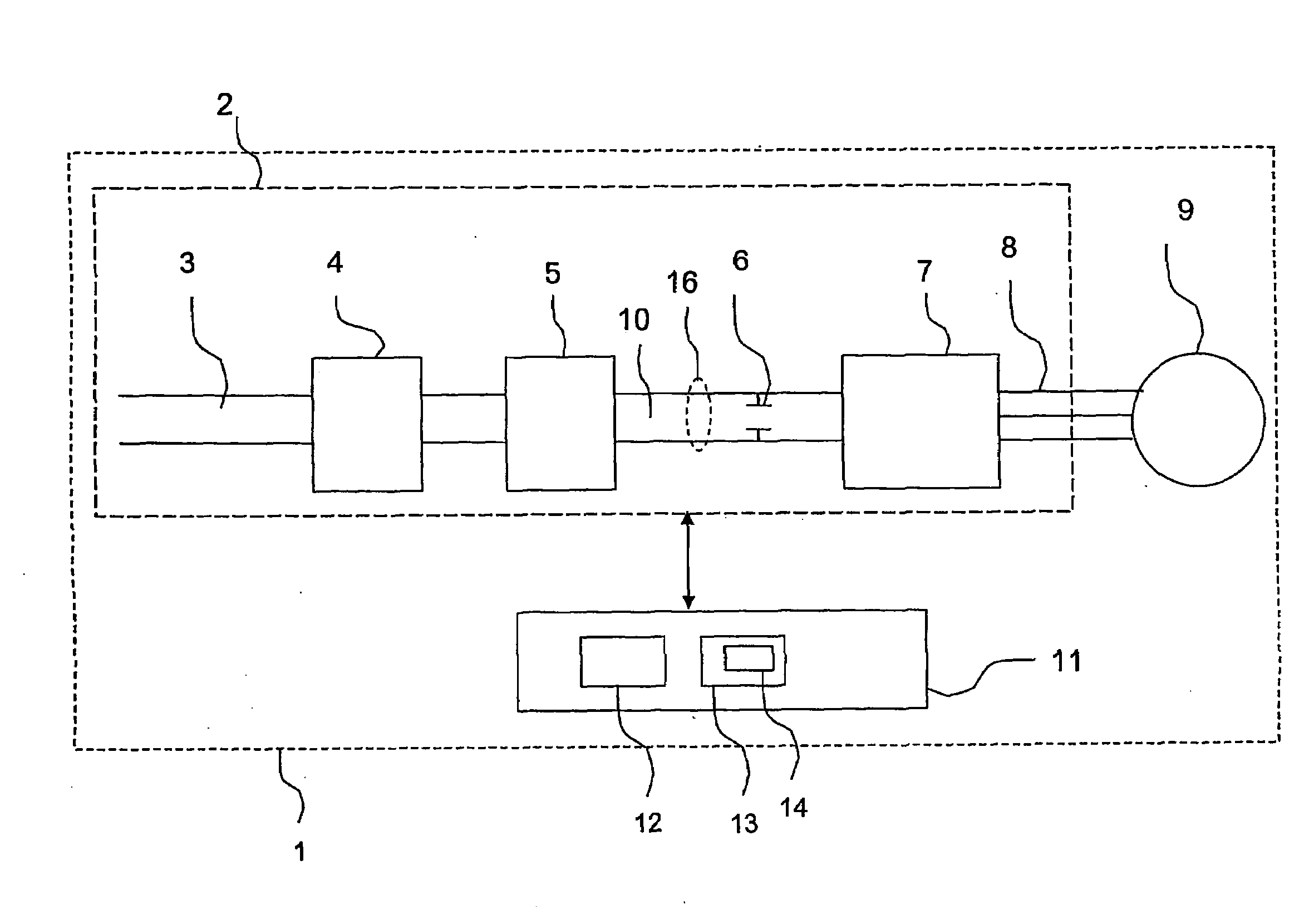
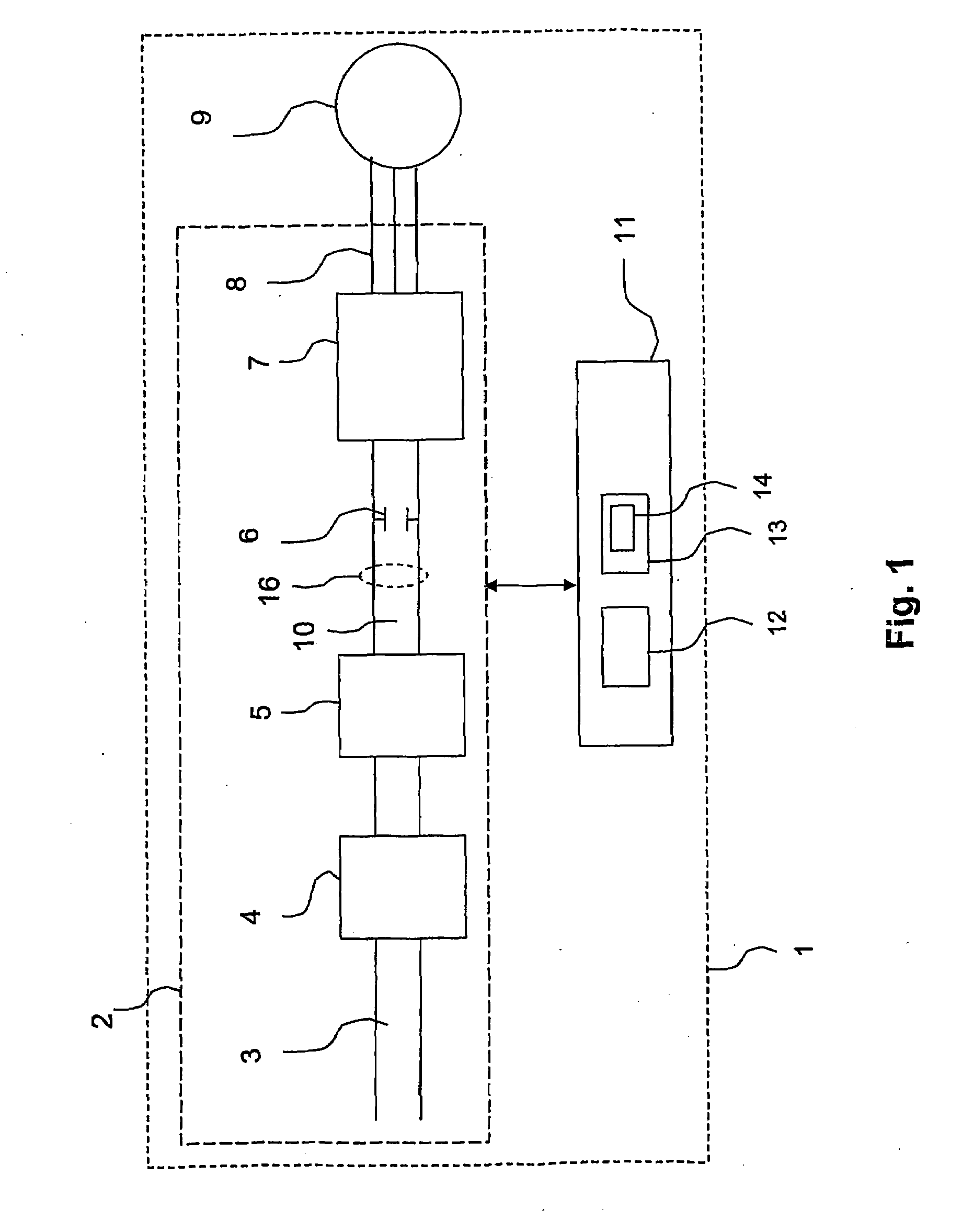
Another known problem with pumps comprising conventional variable frequency drive means, is that the latter is usually mounted distant from the pump at a dry location
above ground.
More precisely, this necessitates a long
power cable leading from the variable frequency drive means to the motor of the pump, which for conventional variable frequency drive means can result in severe problems with
electromagnetic interference.
However, the operation of the variable frequency drive means in this case is adversely affected by the heat emitted from the motor, which may lead to erroneous operation of the variable frequency drive means.

