Single phase permanent magnet motor and hair dryer using the same

a permanent magnet motor and single phase technology, applied in the direction of synchronous motors, magnetic circuit rotating parts, magnetic circuit shapes/forms/construction, etc., can solve the problems of poor performance stability, complicated fabrication process, unduly large noise, etc., to improve the reliability of the motor startup, reduce the fabrication cost, and simplify the fabrication process

Inactive Publication Date: 2017-03-02
JOHNSON ELECTRIC SA
View PDF40 Cites 3 Cited by
  • Summary
  • Abstract
  • Description
  • Claims
  • Application Information

AI Technical Summary

Benefits of technology

[0023]In the single phase permanent magnet motor of the present invention, the startup angle and cogging torque of the motor are adjustable by adjusting the location / shape of the slot opening, without the need of additional positioning slots or positioning holes formed at the inner surfaces of the poles shoes. This simplifies the fabrication process, reduces the fabrication cost, and improves the motor startup reliability.

Problems solved by technology

However, the uneven air gap may lead to unduly large noise and poor performance stability.
The presence of the positioning holes or slots requires further processing to the stator core, which results in fabrication process being complicated and fabrication cost being increased.

Method used


Image

  • Single phase permanent magnet motor and hair dryer using the same
  • Single phase permanent magnet motor and hair dryer using the same
  • Single phase permanent magnet motor and hair dryer using the same

Examples


first embodiment

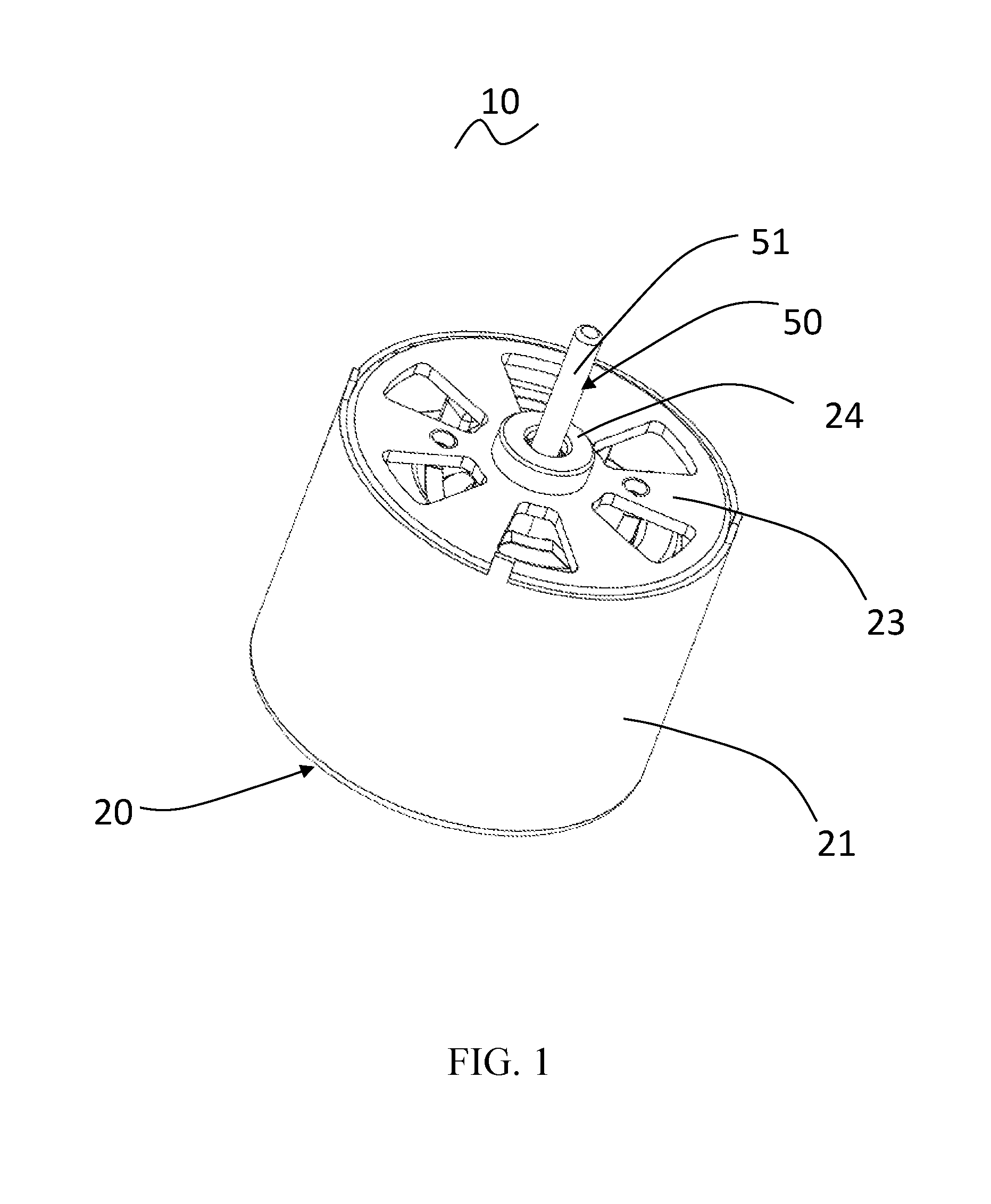
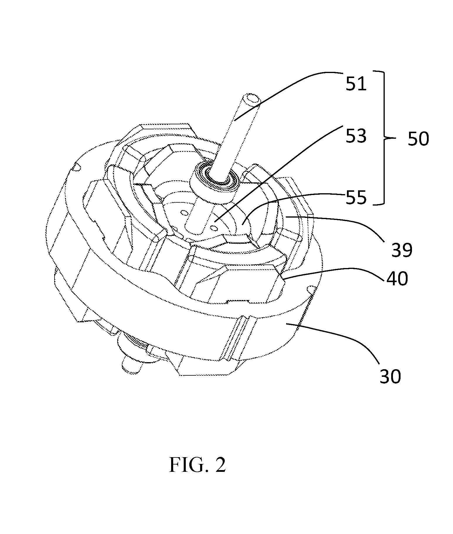
[0040]Referring to FIG. 1 to FIG. 5, a single phase motor 10 in accordance with a preferred embodiment of the present invention includes a stator 20 and a rotor 50 rotatable relative to the stator 20. The single phase motor 10 is preferably a single phase permanent magnet direct circuit brushless motor.

[0041]The stator 20 includes a cylindrical outer housing 21 with one open end, an end cap 23 mounted to the open end of the outer housing 21, a stator core 30 mounted in the outer housing 21, an insulating bracket 40 mounted to the stator core 30, and a stator winding 39 wound around the stator core 30 and supported by the insulating bracket 40. The stator core 30 includes an outer ring portion 31, a plurality of teeth 33 extending inwardly from the outer ring portion 31. Each tooth 33 comprises a tooth body 34 connected to the outer ring portion 31 and two pole shoes 35 extending respectively from a radial inner end to two circumferential sides of the tooth body 34 of each tooth 33. ...

second embodiment

[0049]Referring to FIG. 7, different from the first embodiment, in order to increase the winding efficiency of the stator winding 39, the stator core of the second embodiment includes a plurality of stator core units 300 joined along a circumferential direction of the stator. Each stator core unit 300 includes a tooth 303 with a pole shoe 305, and a yoke segment 301 integrally connected with the tooth 303. The yoke segments 301 of adjacent stator core units are connected together to form the outer ring portion of the stator core. It should be understood that, each stator core unit may also include more than one tooth 303 and corresponding pole shoes 305. After the winding process of all stator core units is completed, the stator core units 300 are joined, thus achieving the stator core with the stator winding. In this embodiment, each stator core unit 300 includes one tooth 303 and its corresponding pole shoe 305, and in each stator core unit 300, one end of the tooth 303 is connect...

third embodiment

[0053]Referring to FIG. 9, in this embodiment, the stator core includes a plurality of stator core units 310 joined along the circumferential direction of the stator. Each stator core unit 310 includes a tooth 313 with a pole shoe 315, and a yoke segment 311 integrally connected with the tooth 313. The yoke segments 311 of adjacent stator core units are connected together to form the outer ring portion of the stator core. It should be understood that, each stator core unit may also include more than one tooth 313 and corresponding pole shoes 315. After the winding process of all stator core units is completed, the stator core units 300 are joined, thus achieving the stator core having the stator winding. In this embodiment, each stator core unit 310 includes one tooth 313 and its corresponding pole shoe 315, and in each stator core unit 310, one end of the tooth 313 is connected to the yoke segment 311 between two ends of the segment 311.

[0054]In this embodiment, the joining faces o...


PUM


Abstract

A single phase motor and a hair dryer are provided. The motor includes a stator and a rotor. The stator includes a stator core and a stator winding. The stator core includes an outer ring portion, teeth extending inwardly from the outer ring portion, and two pole shoes extending from a distal end of each tooth. A winding slot is formed between each two adjacent teeth. A slot opening is disposed between the pole shoes of the adjacent teeth, and is offset from one of the two adjacent teeth. The air supplying unit includes the single phase motor and an impeller. The startup angle and cogging torque of the motor are adjustable by adjusting the position/width of the slot opening, without the need of additional positioning slots or positioning holes defined at the pole shoes, which makes the motor structure simple.

Description

CROSS REFERENCE TO RELATED APPLICATIONS[0001]This non-provisional patent application claims priority under 35 U.S.C. §119(a) from Patent Application No. 201510545984.6 filed in The People's Republic of China on 28 Aug. 2015.FIELD OF THE INVENTION[0002]The present invention relates to a single phase permanent magnet motor, and in particular to a single phase permanent magnet motor with an even air gap and a hair dryer using the motor.BACKGROUND OF THE INVENTION[0003]A single phase permanent magnet motor includes a stator and a rotor. The stator includes a stator core and a stator winding wound around the stator core. The stator core includes pole shoes surrounding around the rotor. The pole shoes and the rotor define an air gap there between, for allowing the rotor to rotate relative to the stator.[0004]Traditionally, in order to avoid a startup dead point of the single phase permanent magnet motor, the air gap is often configured to be an uneven air gap or positioning holes or slots...

Claims


Application Information

Patent Timeline
Patent Type & Authority Applications(United States)
IPC IPC(8): A45D20/12H02K19/04H02K1/27H02K3/12H02K1/14H02K1/16
CPCA45D20/12H02K1/145H02K19/04H02K1/2706H02K3/12H02K1/16A45D20/10H02K1/148H02K21/16H02K2213/03H02K1/278H02K29/03H02K1/14H02K2201/03
Inventor LI, YUEZHOU, CHUI YOUCHAI, JIEZHANG, TAOZHOU, QIANG
Owner JOHNSON ELECTRIC SA
Why Eureka
Try Eureka