Single Phase Permanent Magnet Motor

a permanent magnet motor, single-phase technology, applied in the direction of dynamo-electric machines, magnetic circuit rotating parts, magnetic circuit shapes/forms/construction, etc., can solve the problems of motor vibration and noise, motor startup angle small, motor generates unduly large cogging torque,

Active Publication Date: 2017-03-16
JOHNSON ELECTRIC SA
View PDF9 Cites 3 Cited by
  • Summary
  • Abstract
  • Description
  • Claims
  • Application Information

AI Technical Summary

Benefits of technology

[0004]Thus, there is a desire for a new single phase permanent magnet motor with improved startup reliability.
[0023]The single phase permanent magnet motor of the present invention uses different types of stator core laminations with different structures that are stacked to form the stator core, which obtains the advantages of different stator core laminations while overcoming or reducing the shortcomings caused by the use of a single type of core laminations.

Problems solved by technology

In the single phase permanent magnet motor as such configured, the presence of the large slot openings can make the motor generate an unduly large cogging torque.
The cogging torque can result in the motor generating vibration and noise.
Furthermore, because of the limitation of the large slot openings, the motor has a small startup angle and poor startup reliability

Method used


Image

  • Single Phase Permanent Magnet Motor
  • Single Phase Permanent Magnet Motor
  • Single Phase Permanent Magnet Motor

Examples


first embodiment

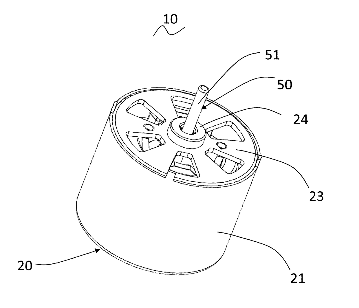
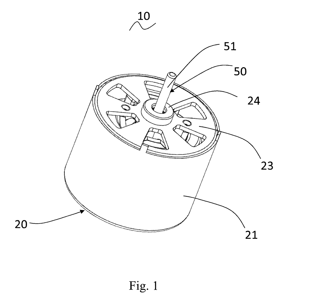
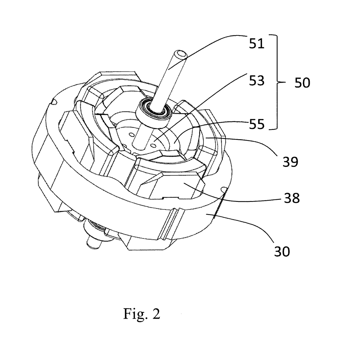
[0040]Referring to FIG. 1 to FIG. 5, the single phase permanent magnet motor 10 in accordance with a first embodiment of the present invention includes a stator 20 and a rotor 50 rotatable relative to the stator.

[0041]The stator 20 includes a cylindrical outer housing 21 with one open end, an end cap 23 mounted to the open end of the outer housing 21, a stator core 30 mounted in the outer housing 21, an insulating bracket 38 mounted to the stator core 30, and a winding 39 wound around the stator core and supported by the insulating bracket 38. The stator core 30 is formed by stacking a plurality of first stator core laminations 310 and a plurality of second stator core laminations 320. Each first stator core lamination 310 includes a first outer ring portion 311, a plurality of first tooth bodies 313 extending inwardly from the first outer ring portion 311, and a first pole shoe 315 extending from a distal end to two circumferential sides of each first tooth body 313, with a first s...

second embodiment

[0050]Referring to FIG. 7 and FIG. 8, different from the first embodiment, in order to increase the winding efficiency of the winding 39, the first stator core lamination 310 includes a plurality of first stator core parts 300 joined along a circumferential direction of the stator. Each first stator core part 300 includes a first arcuate yoke segment 311b, a first tooth body 313 extending from the first arcuate yoke segment 311b, and a first pole shoe 315 extending from a radial distal end of the first tooth body 313 to two circumferential sides of the first tooth body 313. In this embodiment, each first stator core part 300 includes a single first tooth body 313 and one associated first pole shoe 315. It should be understood that, each stator core part may also include more than one first tooth bodies 313 and corresponding first pole shoes 315. The second stator core lamination 320 also includes a plurality of second stator core parts 300b joined along the circumferential direction...

third embodiment

[0056]Referring to FIG. 10, in this embodiment, the rotor 70 includes a plurality of permanent magnetic poles 75 arranged along a circumferential direction of the rotor. An outer surface of each permanent magnetic pole 75 is an arc surface. The outer circumferential surface of the permanent magnetic pole 75 is spaced from a center of the rotor 70 by a distance that progressively decreases from a circumferential center to two circumferential ends of the outer circumferential surface. The stator may be the same as the stator of the embodiments above. When the inner surfaces of the first pole shoe 315 and the second pole shoe 325 are located on a cylindrical surface centered at the center of the rotor, the permanent magnetic poles 75 and the inner circumferential surfaces of the first pole shoes 315 and second pole shoes 325 form therebetween a symmetrical uneven air gap. Preferably, the symmetrical uneven air gap has a maximum thickness that is at least 1.5 times of its minimum thickn...


PUM


Abstract

A single phase permanent magnet motor includes a stator and a rotor relative to the stator. The stator includes a stator core with a winding wound therearound. The stator core includes stacked first and second stator core laminations. The first stator core lamination includes a plurality of first pole shoes. The second stator core lamination includes a plurality of second pole shoes. The structures of the first pole shoes and the second pole shoes are different. The first pole shoes and the second pole shoes are stacked substantially along the axial direction of the motor. The present invention reduces vibration and noise caused by the use of a single type of core laminations in the prior art.

Description

CROSS REFERENCE TO RELATED APPLICATIONS[0001]This non-provisional patent application claims priority under 35 U.S.C. §119(a) from Patent Application No. 201510575665.X filed in The People's Republic of China on Sep. 10, 2015.FIELD OF THE INVENTION[0002]The present invention relates to a single phase permanent magnet motor, and in particular to a single phase permanent magnet motor having a laminated stator core.BACKGROUND OF THE INVENTION[0003]In a conventional single phase permanent magnet motor, a stator core is provided as an integral structure, i.e. an outer ring portion and teeth of a stator core are formed at the same time into an integral structure. Large slot openings are formed between pole shoes of adjacent teeth for facilitating the winding of windings. In the single phase permanent magnet motor as such configured, the presence of the large slot openings can make the motor generate an unduly large cogging torque. The cogging torque can result in the motor generating vibra...

Claims


Application Information

Patent Timeline
Patent Type & Authority Applications(United States)
IPC IPC(8): H02K1/16H02K1/27
CPCH02K1/27H02K1/16H02K21/16H02K1/146H02K1/278H02K1/24H02K1/265H02K21/14H02K2201/09
Inventor LI, YUEZHOU, CHUI YOUWANG, YONGLI, YONG
Owner JOHNSON ELECTRIC SA
Why Eureka
Try Eureka