

Single-phase permanent magnet motor
A single-phase permanent magnet motor and permanent magnet pole technology, applied to synchronous motors with stationary armatures and rotating magnets, magnetic circuits, electric components, etc., can solve the problems of vibration and noise, poor starting reliability, and small positioning and starting angles And other problems, to achieve the effect of reducing the dead point of starting, enhancing the reliability of starting, and smooth starting and rotation
- Summary
- Abstract
- Description
- Claims
- Application Information
AI Technical Summary
Problems solved by technology
Method used
Image

Examples
no. 1 example
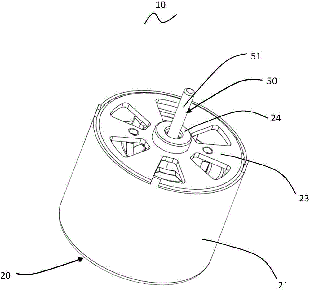
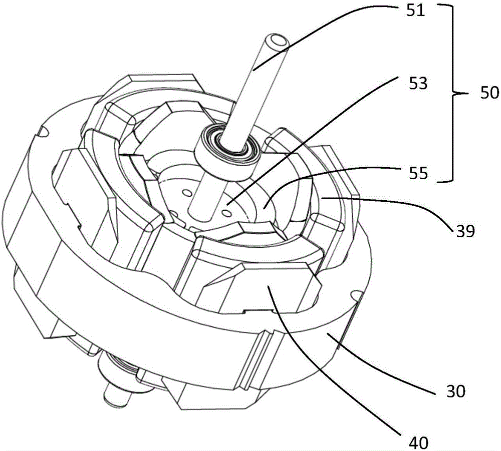
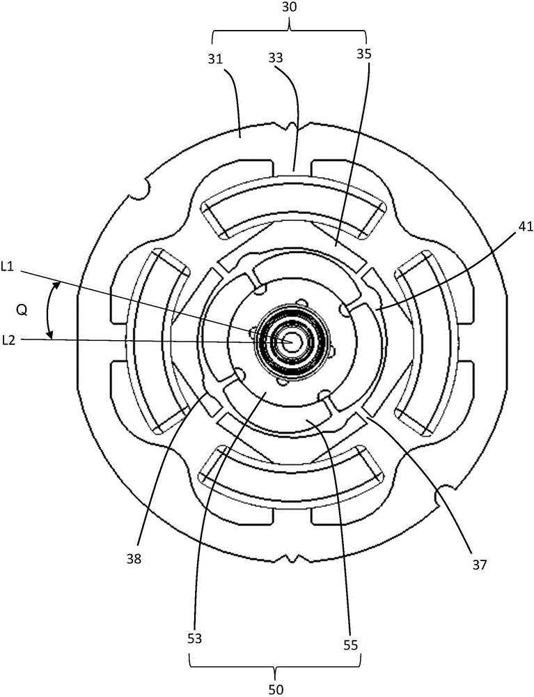
[0034] see Figure 1 to Figure 5 , a single-phase permanent magnet motor 10 in a preferred embodiment of the present invention includes a stator 20 and a rotor 50 that rotates relative to the stator. The stator 20 includes a cylindrical shell 21 with an open end, an end cover 23 mounted to the open end of the shell 21, a stator core 30 mounted in the shell 21, an insulating wire frame 40 mounted to the stator core 30 and wound around the stator core. Winding 39 on core 30 and supported by insulating wire frame 40 . Wherein, the stator core 30 includes an outer ring portion 31, a plurality of tooth bodies 33 protruding inwardly from the outer ring portion 31, a pole piece 35 protruding from the radial end of each tooth body 33 to two sides, and a winding 39 Winding on the corresponding tooth body 33 , the winding 39 is isolated from the stator core 30 by the insulating wire frame 40 .
[0035] The rotor 50 is accommodated in the space surrounded by the pole pieces 35 of the t...
no. 2 example
[0045] Please refer to Figure 7 , and the difference from the previous embodiment is that in order to improve the winding efficiency of the winding 39, the stator core 30 is spliced by several core assemblies 300 along the circumferential direction of the stator, and each core assembly 300 includes an arc-shaped yoke portion 300b 1. The tooth body 33 protrudes from the arc-shaped yoke portion 300b, and the pole piece 35 protrudes from the radial end of the tooth body 33 to both sides in the circumferential direction. In this embodiment, each magnetic core assembly 300 has a tooth body 33 and a corresponding pole piece 35 . Understandably, each magnetic core assembly may also have more than one tooth body 33 and corresponding pole pieces 35 . After the winding of each magnetic core assembly is completed, the several magnetic core assemblies 300 are spliced together to obtain the stator core 30 with stator windings.
[0046] Concave-convex structures are provided at joint...
no. 3 example
[0049] Please refer to Figure 8 , different from the second embodiment, in this embodiment, the joints of the arc-shaped yokes of adjacent magnetic core components are planes, and at this time, the joints of the arc-shaped yokes can be welded together by welding .
PUM
 Abstract
Description
Claims
Application Information