Single-phase brushless motor

A single-phase brushless motor and stator technology, applied in the direction of electric components, electrical components, electromechanical devices, etc., can solve the problems of poor starting reliability, small positioning starting angle, vibration and noise, etc., to improve starting reliability and reduce Activate the dead center effect

Active Publication Date: 2017-03-08
JOHNSON ELECTRIC SHENZHEN
View PDF5 Cites 3 Cited by
  • Summary
  • Abstract
  • Description
  • Claims
  • Application Information

AI Technical Summary

Problems solved by technology

For single-phase brushless motors with this structure, due to the existence of large-sized slots, the motor will generate large cogging torque, resulting in vibration and noise
Moreover, restricted by the notch, the positioning start angle is small, and the start reliability is poor

Method used


Image

  • Single-phase brushless motor
  • Single-phase brushless motor
  • Single-phase brushless motor

Examples


no. 1 example

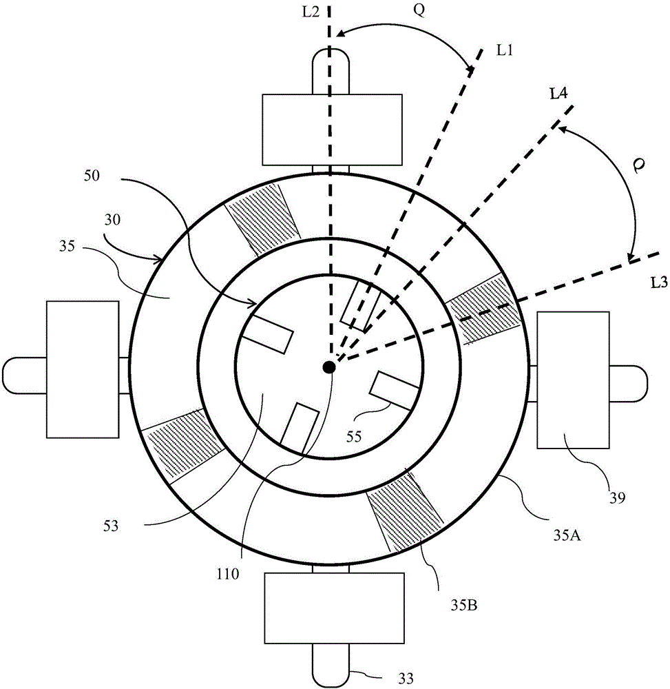
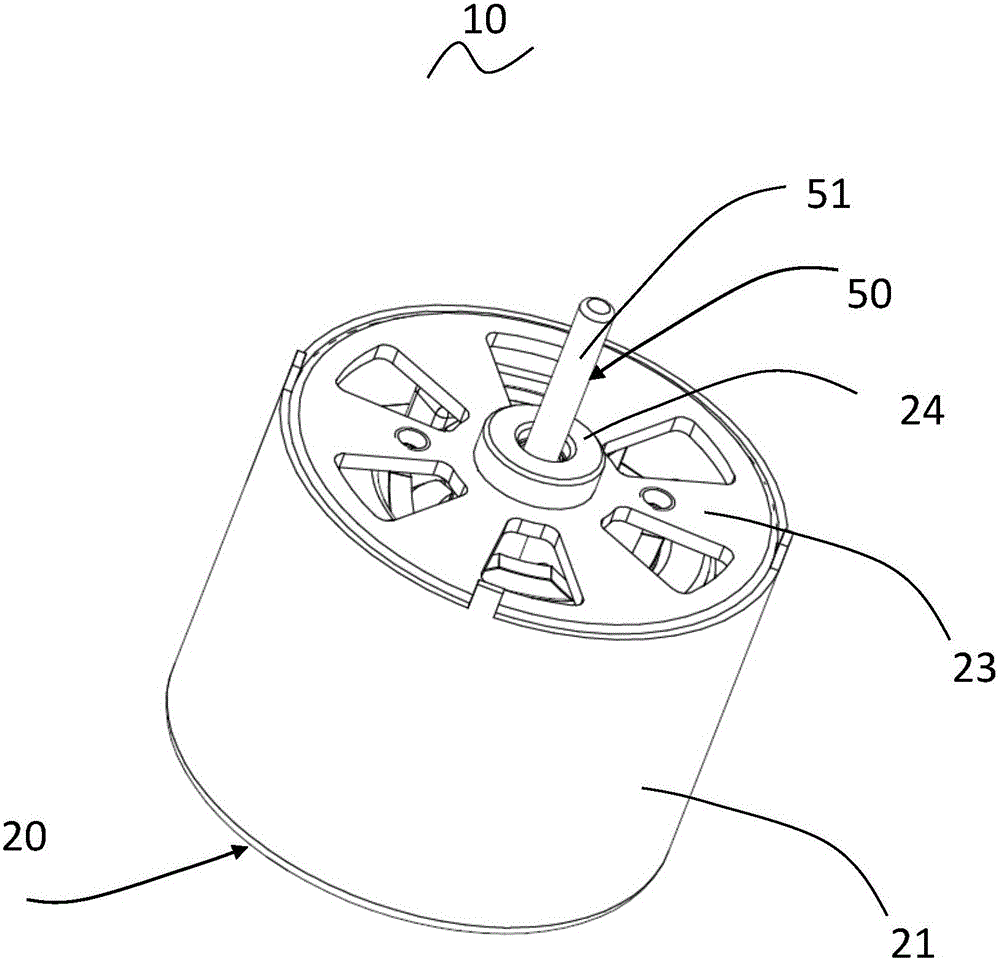
[0049] see Figure 2 to Figure 6 , The single-phase brushless motor 10 provided by the present invention includes a stator 20 and a rotor 50 that can rotate relative to the stator.

[0050] The stator includes a cylindrical shell 21 with an open end, an end cover 23 mounted to the open end of the shell 21, a stator core 30 mounted in the shell 21, an insulating wire frame 40 mounted to the stator core 30 and wound around the stator core. Winding 39 on and supported by insulating wire frame 40. The stator core 30 includes an outer yoke 31 , a plurality of teeth 33 protruding inward from the outer yoke 31 , and pole pieces 35 protruding from the radially inner ends of the teeth 33 to both sides in the circumferential direction. The winding 39 can preferably be wound on the corresponding tooth body 33 , of course, the winding can also be wound on other parts of the stator core 30 , and the winding 39 and the stator core 30 are isolated and insulated by the insulating wire frame ...

no. 2 example

[0062] Please refer to Figure 9 , and the difference from the previous embodiment is that in order to improve the winding efficiency of the winding 39, the stator core adopts a split structure. Specifically, the tooth body 33 and the outer yoke are integrally formed as a whole, and the tooth body 33 and a plurality of teeth The inner ring part formed by connecting the pole pieces of the body is a split structure, that is, the inner ring part and the tooth body 33 are formed separately and then assembled together. It can be understood that each tooth body 33 can be fixedly connected to the inner ring portion by welding or various mechanical connection methods (such as snap-fit ​​method with dovetail groove). In an alternative solution, the tooth body 33 can also be formed separately from the outer yoke portion 31 and the inner ring portion, and the tooth body 33 is fixedly connected to the outer yoke portion 31 and the inner ring portion after the winding 50 is wound. The sta...

no. 3 example

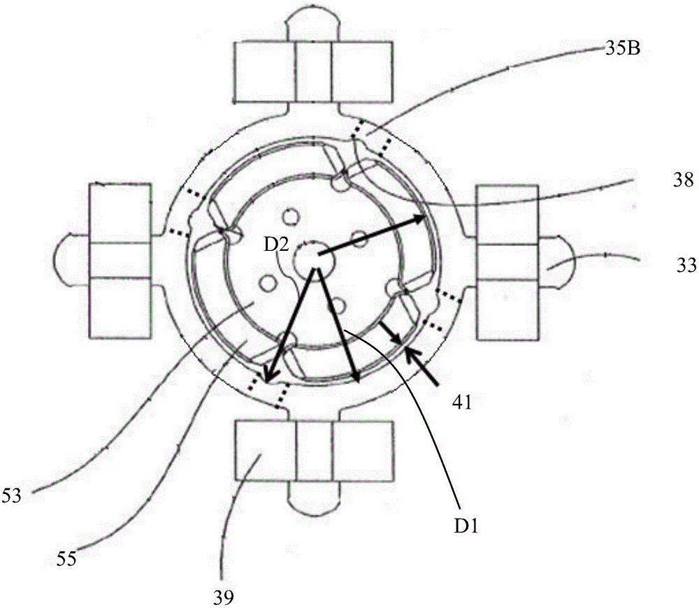
[0064] Please refer to Figure 10 , different from the first embodiment, in this embodiment, grooves 37 are formed on the outer peripheral surface of the inner ring part corresponding to the area of ​​the magnetic bridge, the number of grooves 37 is only one, and its shape is, for example, square, Certainly also can be circular arc or any other shape.

[0065] In this embodiment, the pole shoes 35 between adjacent tooth bodies are also provided with positioning grooves 38. The difference is that the positioning grooves 38 in this embodiment are located in the inner ring formed by connecting pole shoes of several tooth bodies. The invisible positioning groove is between the outer peripheral surface and the inner peripheral surface of the part, preferably, close to the inner peripheral surface of the inner ring part. In this way, the distance between the first arc portion and the second arc portion of the pole piece 35 and the rotor axis is equal.

[0066] In this embodiment, ...


PUM


Abstract

The invention provides a single-phase brushless motor, which comprises a stator and a rotor, wherein the stator comprises a stator core and windings wound on the stator core; the stator core comprises outer yokes, tooth bodies extending inwards from the corresponding outer yokes, and pole shoes extending towards two circumferential sides from radial inner ends of the corresponding tooth bodies; an accommodating space is enclosed by the pole shoes; the rotor is accommodated into the space and comprises a plurality of magnetic poles; the distance from the peripheral surface of each magnetic pole to the axis of the rotor is gradually reduced from the circumferential center to the two circumferential sides; each pole shoe comprises a first arc-shaped part and a second arc-shaped part; the center of each first arc-shaped part deviates from the center of the corresponding tooth body; and when the windings are not electrified, the acting force between one first arc-shaped part and the corresponding magnetic pole is greater than that between the corresponding second arc-shaped part and magnetic pole, so that the center of the corresponding magnetic pole deviates from the center of the corresponding tooth body. According to the single-phase brushless motor, the startup reliability of the motor is improved and possible startup dead points are reduced.

Description

technical field [0001] The invention relates to a single-phase brushless motor, in particular to a single-phase brushless motor with symmetrical and non-uniform air gaps. Background technique [0002] The motor stator core of the single-phase brushless motor in the prior art adopts an integral structure, that is, the outer yoke and the teeth of the stator core are formed into an integrated structure at the same time, and a larger size is set between the pole shoes of the adjacent teeth. notch. The single-phase brushless motor with this structure, due to the existence of a large slot, will cause the motor to generate a large cogging torque, thereby generating vibration and noise. Moreover, restricted by the notch, the positioning starting angle is small, and the starting reliability is poor. [0003] In view of this, the present invention aims to provide a novel single-phase brushless motor capable of improving starting reliability. Contents of the invention [0004] The...

Claims


Application Information

Patent Timeline
Patent Type & Authority Applications(China)
IPC IPC(8): H02K29/03H02K21/14H02K1/27
CPCH02K1/276H02K21/14H02K29/03
Inventor 李越周垂有王勇李勇
Owner JOHNSON ELECTRIC SHENZHEN
Why Eureka
Try Eureka