

Single Phase Permanent Magnet Motor
a permanent magnet motor, single-phase technology, applied in the direction of magnetic circuits, electrical apparatus, dynamo-electric machines, etc., can solve the problems of small startup angle, poor startup reliability, unduly large motor cogging torque, etc., to reduce the cogging torque of the motor, improve the reliability of the motor startup, and reduce the effect of vibration and nois
- Summary
- Abstract
- Description
- Claims
- Application Information
AI Technical Summary
Benefits of technology
Problems solved by technology
Method used
Image

Examples
first embodiment
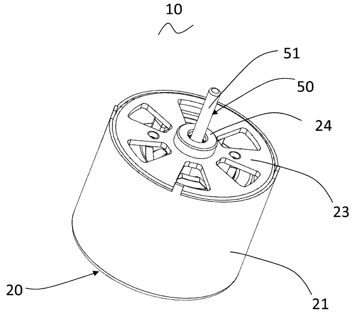
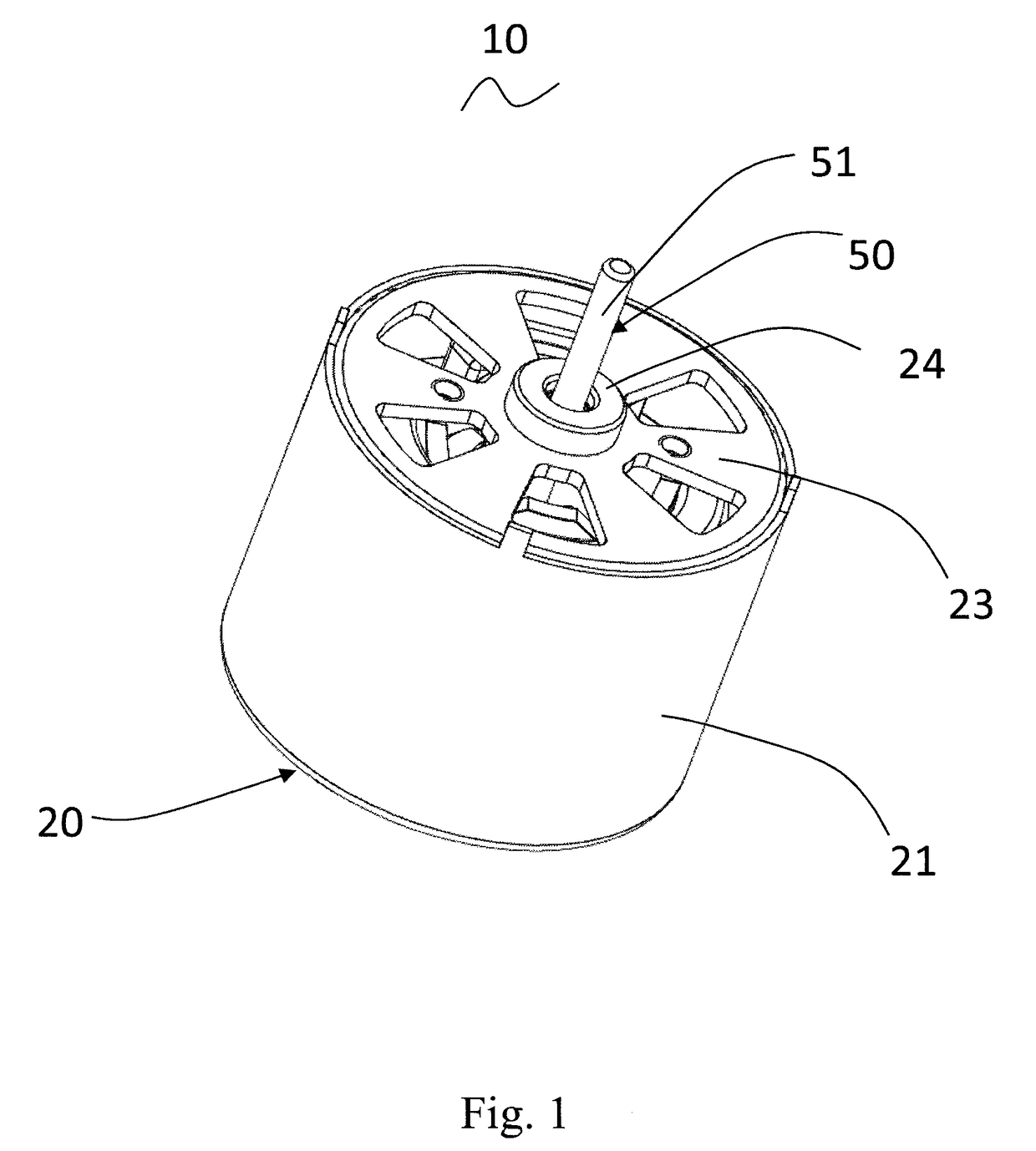
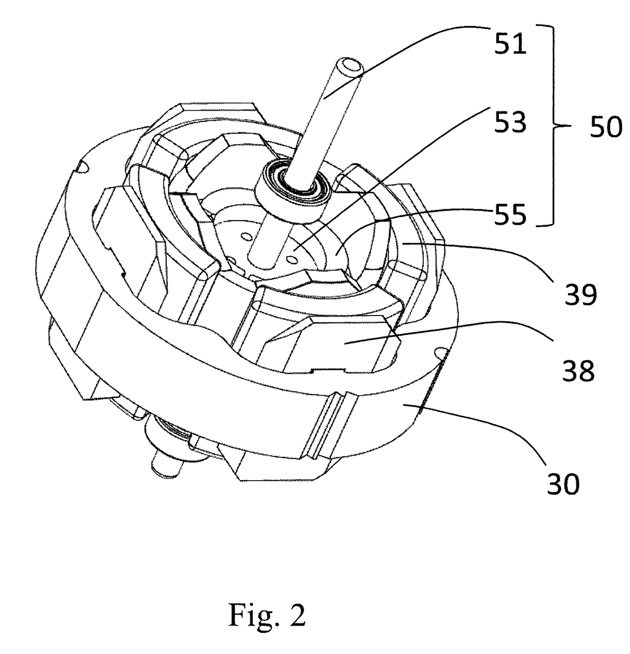
[0042]Referring to FIG. 1 to FIG. 5, the single phase permanent magnet motor 10 in accordance with a first embodiment of the present invention includes a stator 20 and a rotor 50 rotatable relative to the stator.
[0043]The stator 20 includes a cylindrical outer housing 21 with one open end, an end cap 23 mounted to the open end of the outer housing 21, a stator core 30 mounted in the outer housing 21, an insulating bracket 38 mounted to the stator core 30, and a winding 39 wound around the stator core and supported by the insulating bracket 38. The stator core 30 is formed by stacking a plurality of first stator core laminations 310 and a plurality of second stator core laminations 320. Each first stator core lamination 310 includes a first outer ring portion 311, a first inner ring portion 315, and a plurality of first winding portions 313 connected between the first inner and outer ring portions. The second stator core lamination 320 includes a second outer ring portion 321, a plur...
second embodiment
[0052]Referring to FIG. 7, different from the first embodiment, a groove 317 is defined in the outer circumferential surface of the first inner ring portion 313 at a region corresponding to each magnetic bridge 316. The number of the groove 317 is only one. The groove 317 can be of any shape such as circular arc shape or square shape. In addition, the positioning slots 318 are located between the outer circumferential surface and inner circumferential surface of the first inner ring portion 315 and are invisible positioning slots. Preferably, the positioning slots 318 are closer to the inner circumferential surface of the first inner ring portion 315. The positioning slots 318 may be spaced or extend continuously along the axial direction of the motor.
[0053]Referring to FIG. 8, in the present embodiment, the rotor 60 includes a rotor core 63 and ring shaped permanent magnetic poles 65 arranged along a circumferential direction of the rotor 60. An outer circumferential surface of the...
third embodiment
[0056]Referring to FIG. 9 and FIG. 10, different from the first embodiment or the second embodiment, the stator core of this embodiment is of a split-type structure in order to increase the winding efficiency of the stator winding 39. Specifically, the first winding portions 313 and the first outer ring portion 311 are separately formed and then assembled together; in the present embodiment, the first winding portions 313 and the first inner ring portion 315 are integrally formed into an integral structure, and this integral structure is separate from the first outer ring portion 311. Likewise, the second winding portions 323 and the second outer ring portion 321 are separately formed and then assembled together; in the present embodiment, each second winding portions 323 and a corresponding pole shoe 325 are integrally formed into an integral structure, and this integral structure is separate from the second outer ring portion 321. In assembly, the first winding portions 313 and th...
PUM
 Abstract
Description
Claims
Application Information