Image display device and image display method

a display device and image technology, applied in the field of image display devices, can solve the problems of insufficient realism and vigor in the displayed image, insufficient grayscale resolution in shadow portions and highlight portions, and insufficient performance of electronic display devices, etc., to achieve high precision determination, easy detection, and simple configuration

Inactive Publication Date: 2008-05-01
SEIKO EPSON CORP
View PDF8 Cites 52 Cited by
  • Summary
  • Abstract
  • Description
  • Claims
  • Application Information

AI Technical Summary

Benefits of technology

[0075] According to the above configurations, by the image display device of this invention, the grayscales of the image data are detected for all pixels as being within or outside the range of grayscales which can be displayed for the current control values of each of the light sources, so that highly precise determinations can be performed.
[0076] According to the above configurations, by the image display device of this invention, scene changes can easily be detected using a simple configuration, and so devices can be configured at low cost.

Problems solved by technology

In addition, grayscale resolution in shadow portions and in highlight portions is insufficient.
For this reason, there is a sense of insufficient realism and vigor in the displayed image.
However, because the performance of electronic display devices is inadequate, when displaying the above CG content images, there is the problem in that the expressiveness (the number of bits representing grayscales) inherent in the images of CG content cannot be adequately displayed.
Hence, in the methods of the above-described references, the distribution information or the like for the light sources result in a large amount of data and extreme complexity, and when illumination distributions are to be determined by computation, the circuitry and processing time required for computation are considerable.
Furthermore, when values calculated in advance are stored and are then read out, there is the problem in that large memory capacity is necessary to store illuminations for each pixel corresponding to the above-described distribution information.
In particular, in the methods of the above-described references, processing time for computation is increased, and time is required to read illuminations for each pixel from memory, so that real-time calculation of illuminations for each pixels is difficult, and motion images cannot be displayed.
Moreover, the problem of the need for a large amount of time and memory for the above-described computation processing increases exponentially as the number of light sources and the number of control steps of the light source brightness increase.

Method used


Image

  • Image display device and image display method
  • Image display device and image display method
  • Image display device and image display method

Examples


first embodiment

[0089] Below, the image display device of a first embodiment of the invention is explained, referring to the drawings.

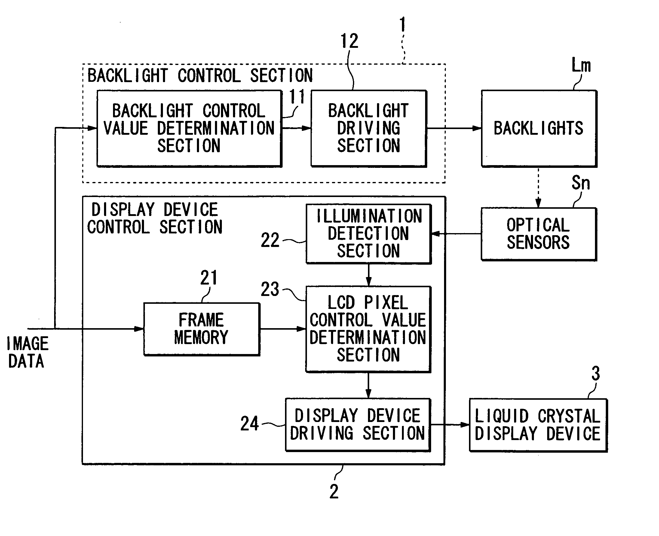
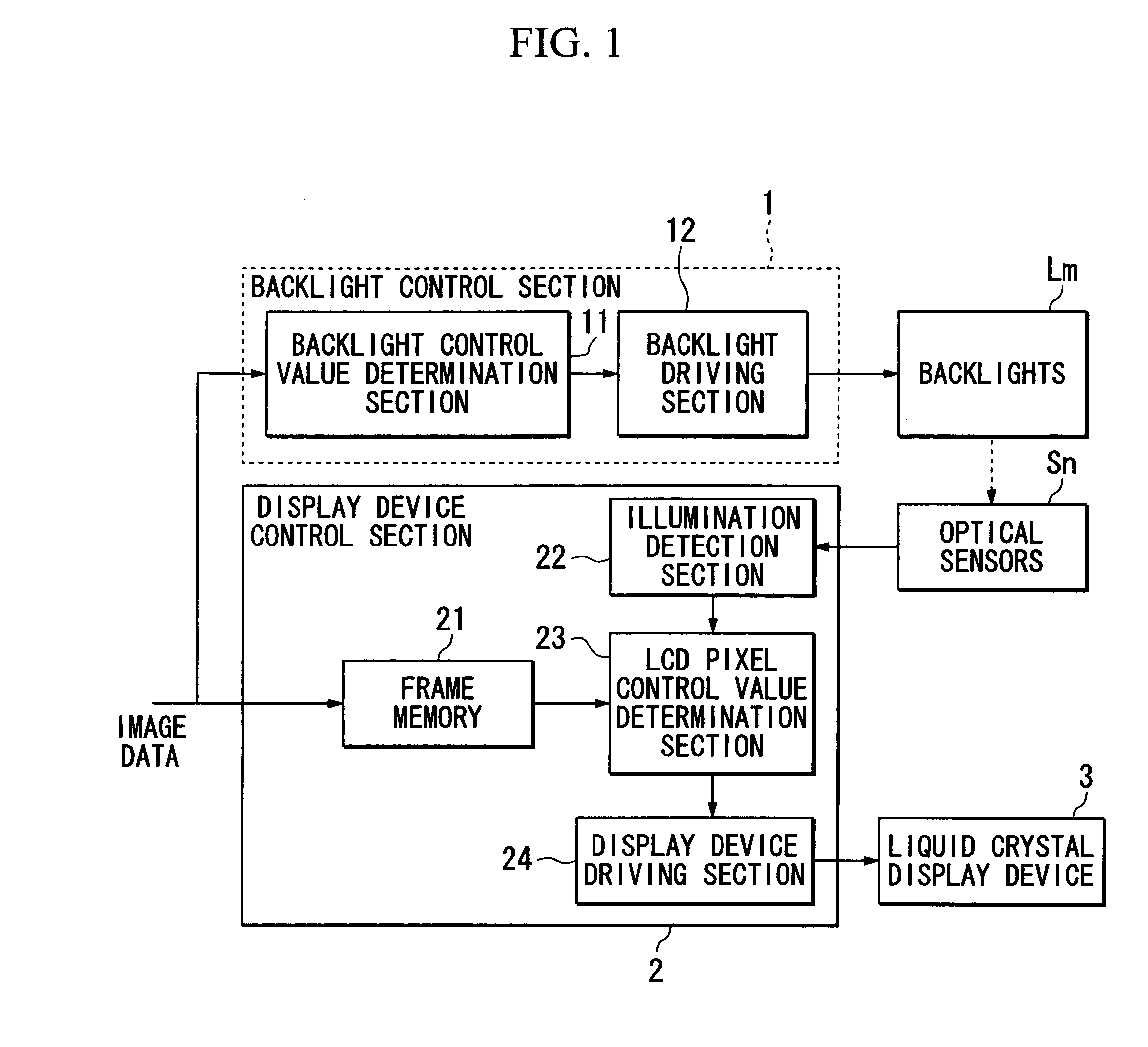
[0090]FIG. 1 is a block diagram showing an example of the configuration of the embodiment.

[0091] In the figure, the backlight control section 1 independently controls each of the backlights (light sources) (for example, if there are m backlights, then the backlights are L1 through Lm) provided on the optical modulation element, which for example is a liquid crystal display device 3.

[0092] The backlight control section 1 includes a backlight control value determination section 11 and a backlight driving section 12.

[0093] The backlight control value determination section 11 detects, in the input image data, the maximum grayscale value (highest luminance value) among the grayscales of the image data corresponding to pixels included in the pixel area associated with each of the above backlights, and determines the brightness control value (backlight control value) fo...

second embodiment

[0201] Below, the image display device of a second embodiment of the invention is explained, referring to the drawings.

[0202]FIG. 8 is a block diagram showing an example of the configuration in this embodiment.

[0203] In the figure, sections which are similar to those of the first embodiment in FIG. 1 are assigned the identical symbols, and explanations are omitted.

[0204] Below, the configuration and operation are explained only with respect to differences with the first embodiment.

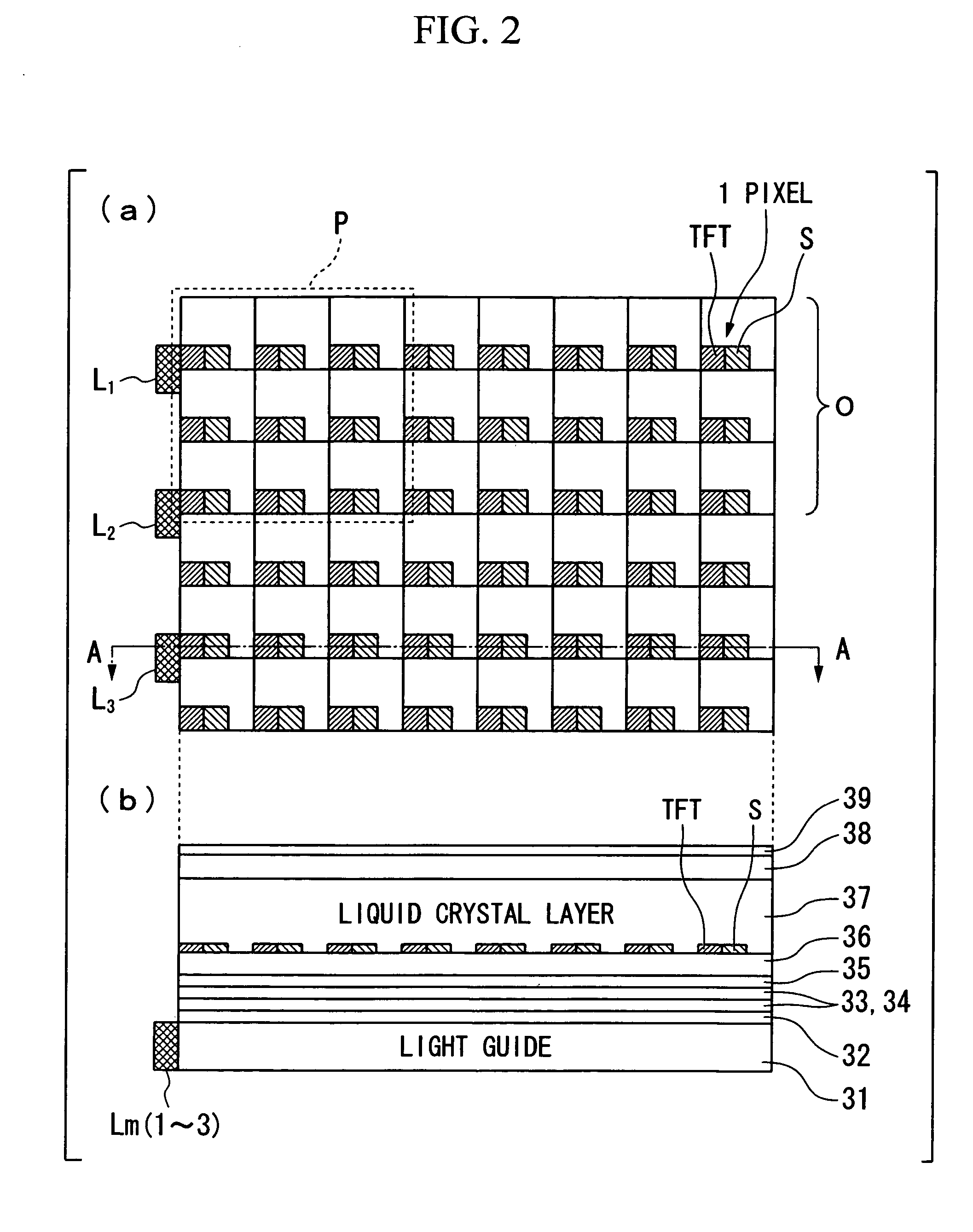
[0205] In this embodiment, optical sensors S are provided in each of the three sub-pixels, for R (red), G (green), and B (blue), which form one pixel.

[0206] As explained above, the sub-pixels in this embodiment correspond to R, G, and B pixels.

[0207] In this embodiment, a single sub-pixel is explained as follows, similarly to a single pixel in the first embodiment.

[0208] The backlight control value determination section 11 determines backlight control values corresponding to the R, G, and B grayscal...


PUM


Abstract

An image display device includes: an optical modulation element having a plurality of pixels; light sources illuminating the optical modulation element, each of which is independently controlled; a light source control value setting section setting control values for each of the light sources according to the grayscale of each pixel of an input image; optical sensors provided on areas of “n” pixels, respectively, where the “n” is an integer equal to or greater than 1; an illumination detection section detecting the illumination of the areas by the optical sensors; and a grayscale control section processing to correct grayscale of each pixel based on the detected illumination and controlling the optical modulation element according to the corrected grayscales obtained by correction.

Description

CROSS-REFERENCE TO RELATED APPLICATION [0001] This application claims priority from Japanese Patent Application No. 2006-254506, filed on Sep. 20, 2006, and from Japanese Patent Application No. 2007-230346, filed on Sep. 5, 2007, the entire contents of which are incorporated herein by reference. BACKGROUND [0002] 1. Technical Field [0003] This invention relates to an image display device which displays grayscale images, and in particular relates to an image display device and image display method suitable for display with a large number of grayscales. [0004] 2. Related Art [0005] Recent years have seen stunning improvements in the image quality of LCDs (Liquid Crystal Displays), EL (Electroluminescence) displays, CRTs (Cathode Ray Tubes), projection-type display devices, and other electronic display devices. [0006] Devices are being manufactured which have resolution and color gamut substantially comparable to those of human perception characteristics. [0007] However, the reproducib...

Claims


Application Information

Patent Timeline
Patent Type & Authority Applications(United States)
IPC IPC(8): G09G5/10
CPCG09G3/3426G09G2320/0633G09G2360/16G09G2360/148G09G2320/0646
Inventor NITTA, TAKASHI
Owner SEIKO EPSON CORP
Why Eureka
Try Eureka