Tire pressure detector

a tire pressure detector and detector technology, applied in vehicle tyre testing, instruments, roads, etc., can solve the problems of reducing driving safety, affecting driving safety, and tire pressure being too low,

Active Publication Date: 2007-03-01
HUANG TENG WEN
View PDF14 Cites 50 Cited by
  • Summary
  • Abstract
  • Description
  • Claims
  • Application Information

AI Technical Summary

Benefits of technology

[0009] Furthermore, the cover is provided with an air inflation nozzle which has a channel in communication with the airtight chamber. The channel has a check val

Problems solved by technology

When tire pressure is too low or tire temperature is too high, driving safety is adversely affected.
In addition, due to high rotational speeds when driving and imperfect airtightness of the tire valve stem, air inside the tire gradually leaks out, which causes the tire pressure to be too low and thus decreases driving safety.
When the tire pressure is insufficient, the tire pressure fails in confronting the resilience of the resilient member, and so fails in upwardly pushing the resilient member and the pushing rod and the metal contact board on the resilient member.
Furthermore, the tire pressure alarm device transmits a

Method used


Image

  • Tire pressure detector
  • Tire pressure detector
  • Tire pressure detector

Examples


first embodiment

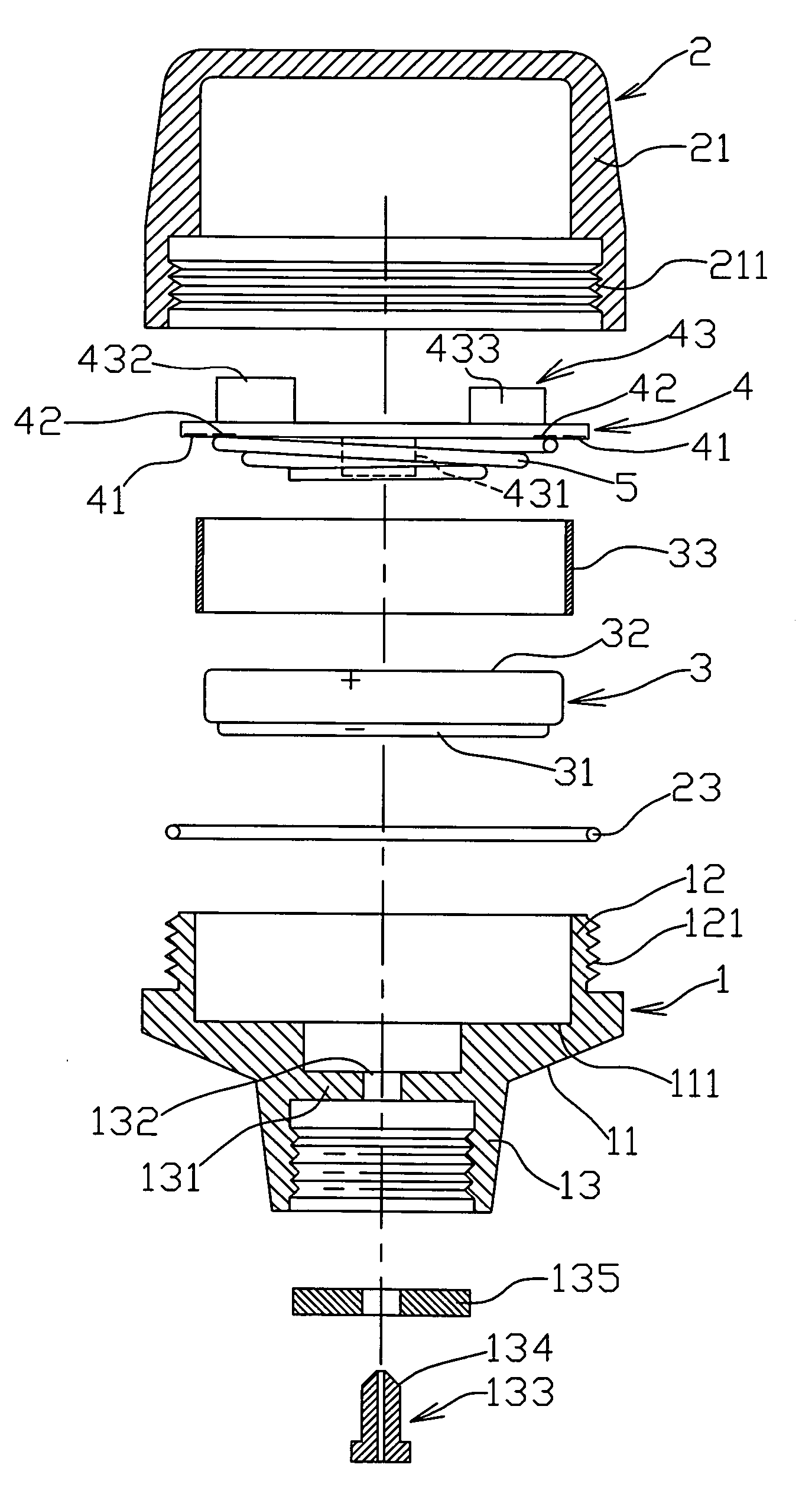
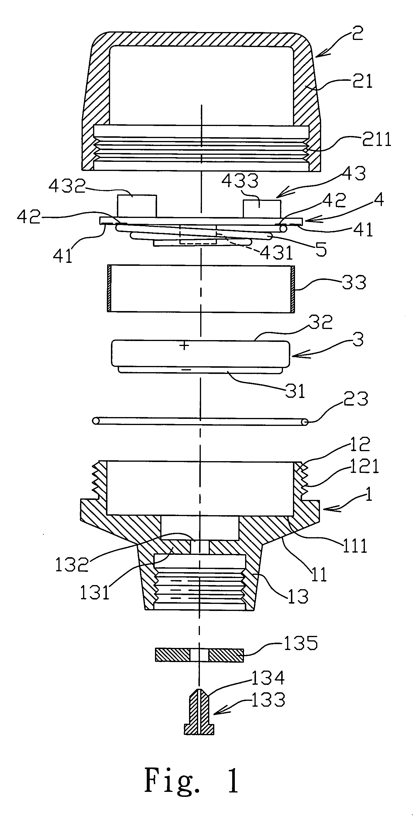
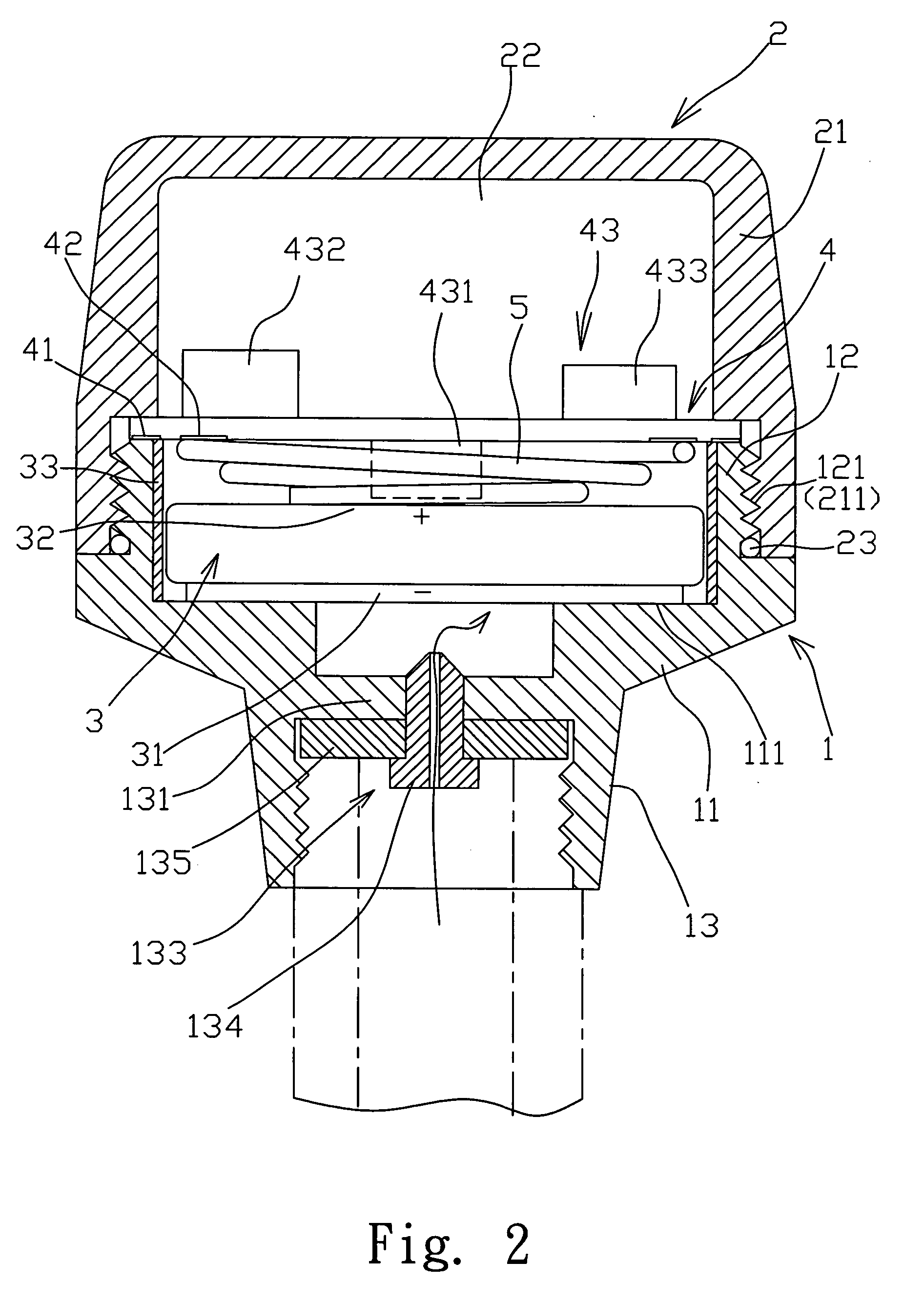
[0019] The present invention is described with reference to the attached drawings. FIG. 1 is an exploded view of a tire pressure detector in accordance with the present invention, FIG. 2 is a cross-sectional view of an assembled tire pressure detector of FIG. 1, and FIG. 3 is a schematic view showing the tire pressure detector of FIG. 2 being disposed at a tire valve stem.

[0020] As shown in the drawings, the tire pressure detector of the present invention includes an electrically conductive housing 1, a cover 2, a battery device 3, a printed circuit board (PCB) 4 and a first electrically conductive resilient member 5.

[0021] The electrically conductive housing 1 has a housing body 11 and a protruding annular body 12. The protruding annular body 12 has an outer thread 121 at the outer surface thereof. A loading portion 111 is formed inside the housing body 11. The housing body 11 has an air intake mouth 13 with a laterally separating seat 131 being formed therein. A central hole 132 ...

second embodiment

[0032] Further referring to FIGS. 5˜7, wherein FIG. 5 is an exploded view of a tire pressure detector in accordance with the present invention, FIG. 6 is a cross-sectional view of an assembled tire pressure detector of FIG. 5, and FIG. 7 is a schematic view showing the tire pressure detector of FIG. 6 being assembled to a tire valve stem.

[0033] The tire pressure detector in accordance with the second embodiment has a generally similar structure and connection relationship to those of the first embodiment of the present invention. That is, the tire pressure detector of the second embodiment includes an electrically conductive housing 1, a cover 2, a battery device 3, a PCB 4 and a first electrically conductive resilient member 5.

[0034] The electrically conductive housing 1 has a housing body 11 and a protruding annular body 12. The protruding annular body 12 has an outer thread 121 at the outer surface thereof. A loading portion 111 is formed inside the housing body 11. The cover 2 ...


PUM


Abstract

A tire pressure detector includes an electrically conductive housing having a housing body and a protruding annular body; a cover having a sleeve portion connected to the protruding annular body, an airtight chamber defined by the cover and the housing for receiving a battery device, a PCB and a first electrically conductive resilient member, the housing body or the cover being disposed with an air intake mouth; and the PCB having a pressure and temperature detecting device. The air intake mouth guides air inside the tire to flow into the airtight chamber. The pressure and temperature detecting device detects the pressure and temperature of the air inside the tire and transmits data to the microprocessor for processing. The microprocessor controls the transmitter to transmit a signal. A receiver disposed near a driver's seat receives and processes the signal and then displays the tire pressure and temperature value on a display.

Description

RELATED APPLICATIONS [0001] The present application is based on, and claims priority from, Taiwan Application Serial Number 94129955, filed Aug. 31, 2005, the disclosure of which is hereby incorporated by reference herein in its entirety. FIELD OF THE INVENTION [0002] The present invention relates to a tire pressure detector, and particularly to a tire pressure detector which is readily assembled, can avoid short circuiting, and measures in a high precision. BACKGROUND OF THE INVENTION [0003] Regardless of the kinds of vehicles, tires of the vehicles must be inflated to a proper pressure. When tire pressure is too low or tire temperature is too high, driving safety is adversely affected. In addition, due to high rotational speeds when driving and imperfect airtightness of the tire valve stem, air inside the tire gradually leaks out, which causes the tire pressure to be too low and thus decreases driving safety. Therefore, many tire pressure indication devices have been developed for...

Claims


Application Information

Patent Timeline
IPC IPC(8): B60C23/02
CPCB60C23/0408B60C23/0496
Inventor HUANG, TENG-WEN
Owner HUANG TENG WEN
Why Eureka
Try Eureka