Rotational Angle-Measurement Apparatus and Rotational Speed-Measurement Apparatus

a measurement apparatus and rotational angle technology, applied in the direction of instruments, galvano-magnetic devices, magnetic field measurement using galvano-magnetic devices, etc., can solve the problems of difficult correction of new apparatus, difficult in effect replacement of rotational angle measurement apparatus, and difficult mechanical alignment of magnetic sensors, etc., to achieve enhanced reliability and high accuracy

Active Publication Date: 2010-12-23
HITACHI LTD
View PDF3 Cites 51 Cited by
  • Summary
  • Abstract
  • Description
  • Claims
  • Application Information

AI Technical Summary

Benefits of technology

[0043]According to this invention, measurement of angles with high accuracy becomes possible even in a system where a magnetic substance or material of a high permeability exists in the vicinity of the rotational angle-measurement apparatus.
[0044]According to this invention, a rotational angle-measurement apparatus can be realized which is sufficiently responsive to, that is, able to follow up high-speed rotations.
[0045]According to this invention, reliability can be enhanced by issuing a fault-detection signal when an abnormal condition occurs in a rotational angle-measurement apparatus or a rotational speed-measurement apparatus.

Problems solved by technology

There has hitherto been a problem that when a magnetic sensor is mounted in a conventional rotational angle-measurement apparatus using magneto-resistance elements, the mechanical alignment of the magnetic sensor is difficult.
Such a conventional rotational angle-measurement apparatus has hitherto suffered from a problem that when it is to be electrically corrected, an actuator / encoder for correction must be prepared and coupled to the apparatus.
Further, the above problems have also led to another problem that correction is difficult if it is attempted after a rotational angle-measurement apparatus has been incorporated in a system, and another problem that if the rotational angle-measurement apparatus already incorporated in a system is replaced by a new one, the correction of the new apparatus is difficult, that is, the replacement of rotational angle-measurement apparatus is difficult in effect.
Moreover, a conventional rotational angle-measurement apparatus has a problem that if there is a magnetic substance or material of a high permeability in the vicinity of the conventional rotational angle-measurement apparatus, accuracy in the measurement of rotational angle is deteriorated.

Method used


Image

  • Rotational Angle-Measurement Apparatus and Rotational Speed-Measurement Apparatus
  • Rotational Angle-Measurement Apparatus and Rotational Speed-Measurement Apparatus
  • Rotational Angle-Measurement Apparatus and Rotational Speed-Measurement Apparatus

Examples


first embodiment

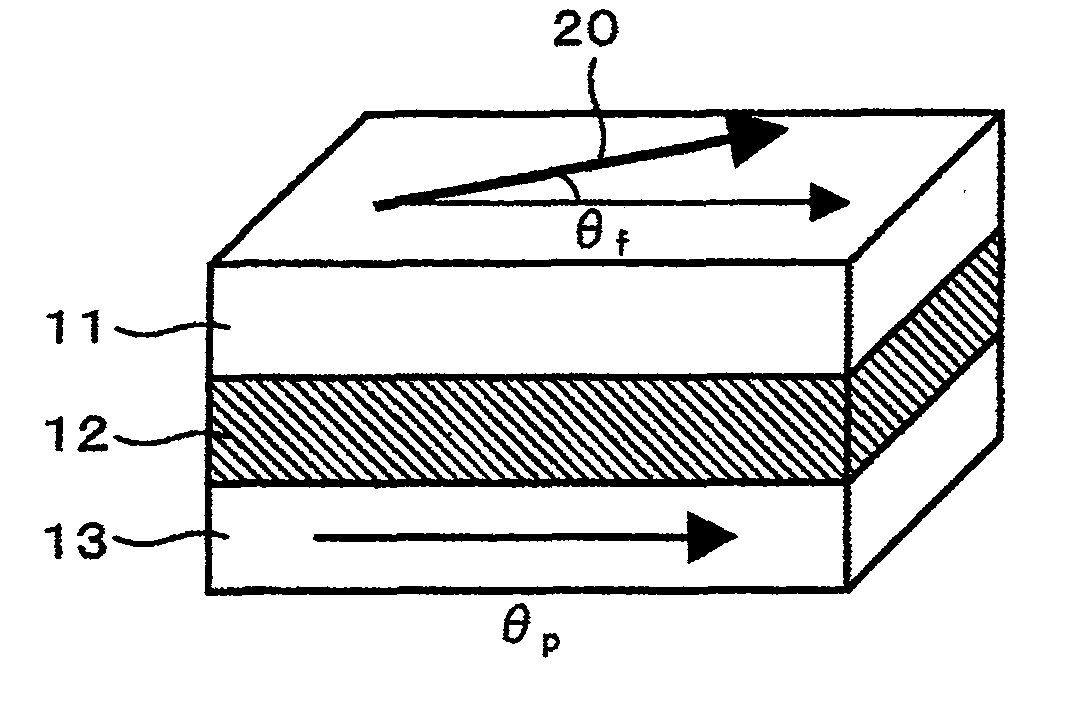
[0078]This invention will now be described in detail below in reference to the attached drawings which show embodiments of this invention. First, a magnetic field detection apparatus according to this invention is exemplified as a magnetic field detection apparatus composed of giant magneto-resistance (GMR) elements.

[0079]FIG. 5 shows a first embodiment of a rotational angle-measurement apparatus according to this invention.

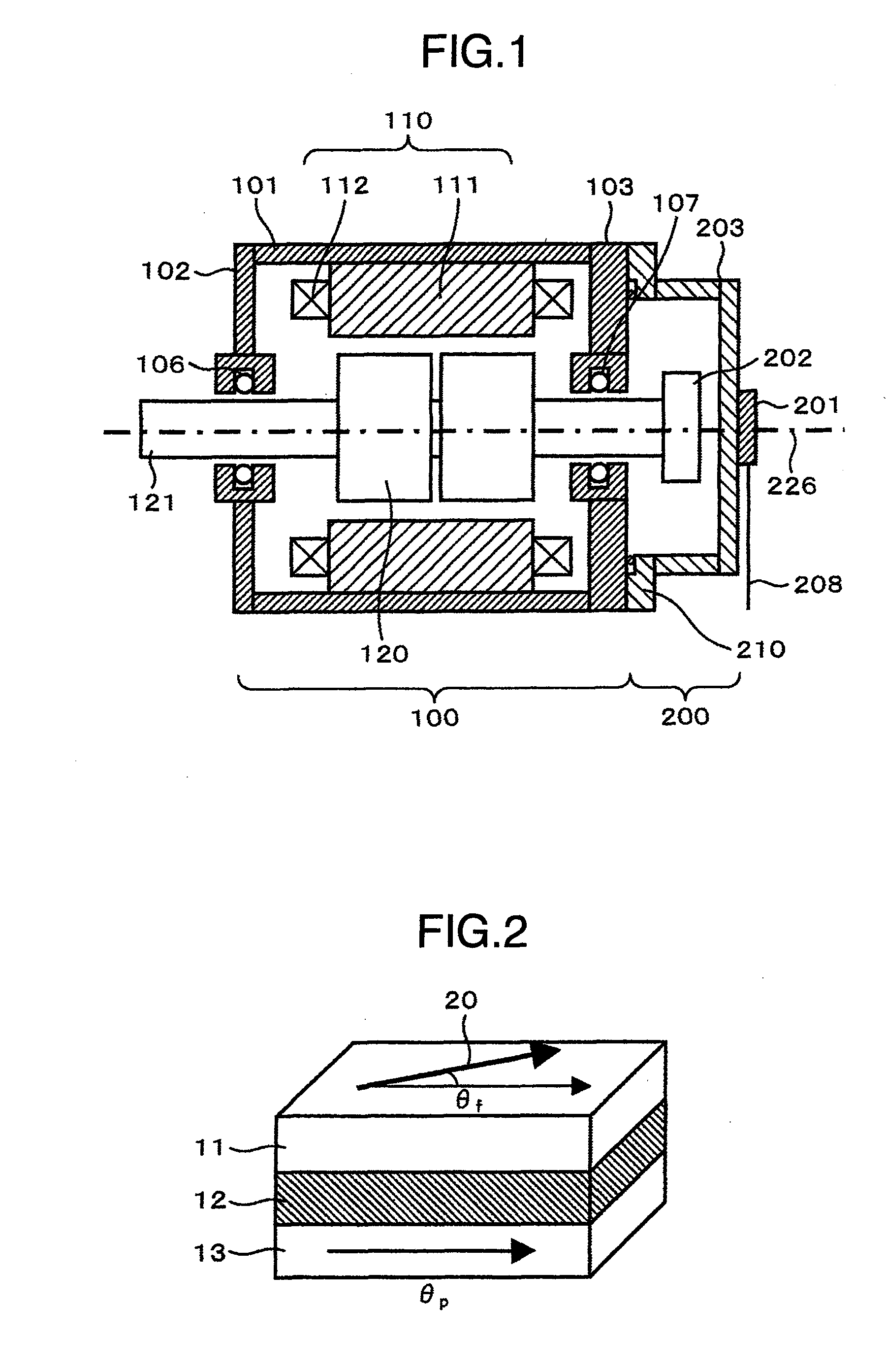
[0080]FIG. 5 is a cross-sectional view of a rotational angle-measurement apparatus as the first embodiment of this invention. This embodiment comprises a motor unit 100 and a rotational angle-measurement unit 200.

[0081]The motor unit 100 comprises a stator 110 consisting mainly of plural fixed magnetic poles and a rotor 120 consisting mainly of plural rotatable magnetic poles. In this motor unit 100, rotational torque is generated through magnetic interaction between the plural fixed magnetic poles and the plural rotatable magnetic poles being rotating. The stato...

second embodiment

[0205]this invention will be described in reference to FIGS. 26 and 27. This embodiment is concerned with a method for improving the temperature characteristic of the magnetic sensor 201 to a great extent.

[0206]Rotational angle sensors have been suffering from a problem that temperature change causes deterioration in measurement accuracy. That is the problem of poor temperature characteristic. According to this embodiment, the temperature characteristic of the magnetic sensor 201 is improved by improving the magnetic field angle-measurement method employed in the magnetic sensor 201.

[0207]The cause for the deterioration of the temperature characteristic in the magneto-resistance element is due to the superposition of offset voltages upon the output signals of the sensor element unit 301 incorporated in the magnetic sensor 201. This point is described in detail below. Since the GMR coefficient G / R in the expression (6) changes with temperature, the value of ΔVc changes with the chang...

third embodiment

[0261]FIG. 29 diagrammatically shows the waveforms of excitation voltages and detecting timing, used in this embodiment, and corresponds to FIG. 27 which is associated with this invention. The positive-polarity pulse 621 for the COS bridge and the positive-polarity pulse 622 for the SIN bridge are applied sequentially with a certain time shift. The negative-polarity pulse 612 is applied to the g terminal.

[0262]As a result of this shifted application of pulses, the signal voltage ΔVc for the COS bridge and the signal voltage ΔVs for the SIN bridge change as shown in FIG. 29. The zero point signal Vz is measured at time t0. Then, the signals for the COS bridge and SIN bridge are obtained at times t1 and t2, respectively.

[0263]In this way, since the signal is measured under the condition that the optimal excitation voltages Δe are applied to the COS and SIN bridges, respectively, then the offset component, that may be otherwise contained in the signal voltage, can be eliminated. Accord...


PUM


Abstract

A rotational angle-measurement apparatus with high accuracy is provided through the electric correction of the rotational angle-measurement apparatus by rotating the rotation shaft at a constant speed.

Description

INCORPORATION BY REFERENCE[0001]The present application claims priority from Japanese Patent Application JP2009-144863 filed on Jun. 18, 2009, the content of which is hereby incorporated by reference into this application.BACKGROUND OF THE INVENTION[0002]This invention relates to a rotational angle-measurement apparatus using magneto-resistance elements (hereafter referred to also as MR elements).[0003]Such a rotational angle-measurement apparatus as using MR elements is disclosed in, for example, JP-3799270.[0004]As MR elements are known anisotropic magneto-resistance elements (hereafter referred to as AMR elements) and giant magneto-resistance elements (hereafter referred to as GMR elements). The general idea of the related, conventional art will be described below with a magnetic field detection apparatus using GMR elements taken as an example.[0005]FIG. 2 shows the fundamental structure of a GMR element. The GMR element comprises a first magnetic layer (pinned magnetic layer), a...

Claims


Application Information

Patent Timeline
Patent Type & Authority Applications(United States)
IPC IPC(8): G01B7/30
CPCG01D5/145G01D5/24428G01D5/24471H02K11/0021G01P3/489H02K11/0005G01P3/487H02K11/215H02K11/0141
Inventor SUZUKI, MUTSUMI
Owner HITACHI LTD
Why Eureka
Try Eureka