Sensor impedance measuring apparatus for improving measurement accuracy of gas sensor

a technology of impedance measurement and sensor, which is applied in the direction of measurement devices, instruments, electrochemical variables, etc., can solve the problems of reducing the accuracy of an output of a sensor, affecting the measurement accuracy of the sensor, and unable to sweep the voltage applied to the sensor element either to the positive or the negative side, so as to ensure the accuracy of the output of the gas sensor and the measurement of the impedance of the sensor element. , to achieve the effect of eliminating the distortion

Inactive Publication Date: 2006-05-18
DENSO CORP
View PDF5 Cites 51 Cited by
  • Summary
  • Abstract
  • Description
  • Claims
  • Application Information

AI Technical Summary

Benefits of technology

[0014] The gas sensor, as already described in the introductory part of this application, may output an electromotive force of approximately 0V. In such an event, it becomes impossible to sweep the voltage applied to the sensor element either to the positive or negative side on the current path leading to the sensor element. The storage device serves to alleviate such a problem in the nature of its acvitity, thus eliminating the distortion of polarization in the sensor element in an impedance measuring mode to ensure the accuracy of output of the gas sensor.
[0015] The gas sensor is designed to use the same cell in measuring the concentration of gas and the impedance of the sensor element. The measurement of the impedance of the sensor element is performed during the measurement of the concentration of gas. There is, therefore, a greater concern about adverse effects of the alternating change in voltage or current used in measuring the impedance on the measurement of the concentration of gas. The capacitor device, however, works to allow the alternating voltage or current to pass therethrough, but block a dc current, thus minimizing the above adverse effects on the measurement of the concentration of gas.
[0016] The measurement of the impedance of the sensor element is achieved by sampling the voltage appearing at an end of the sensor elem

Problems solved by technology

When the sweeping of the voltage is made by shifting the level thereof to only one of positive and negative sides, it may result in distortion of polarization in the sensor element, thus leading to decreased accuracy of an output of the sensor.
The measurement of the impedance of the O2 sensors, however, encounters the following problem.
In such an event, it

Method used


Image

  • Sensor impedance measuring apparatus for improving measurement accuracy of gas sensor
  • Sensor impedance measuring apparatus for improving measurement accuracy of gas sensor
  • Sensor impedance measuring apparatus for improving measurement accuracy of gas sensor

Examples


Embodiment Construction

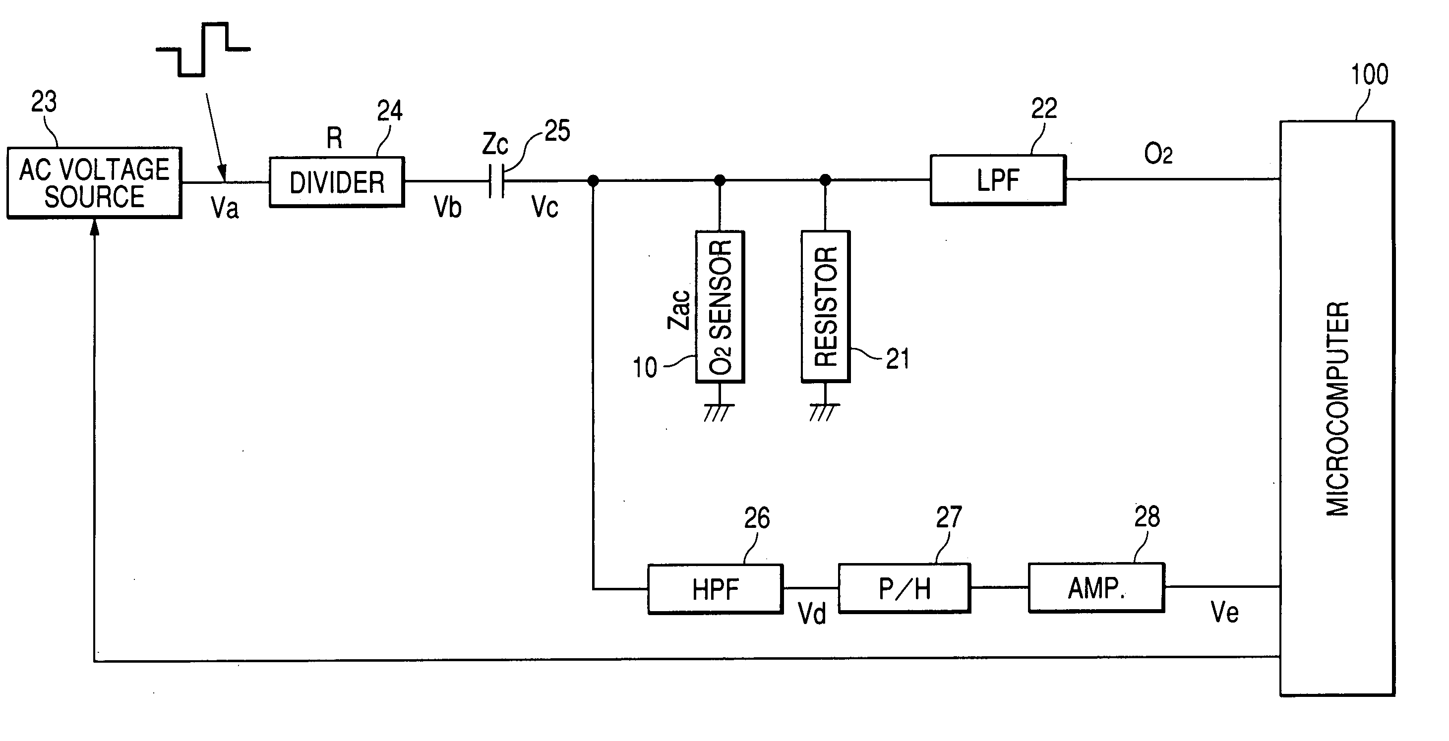
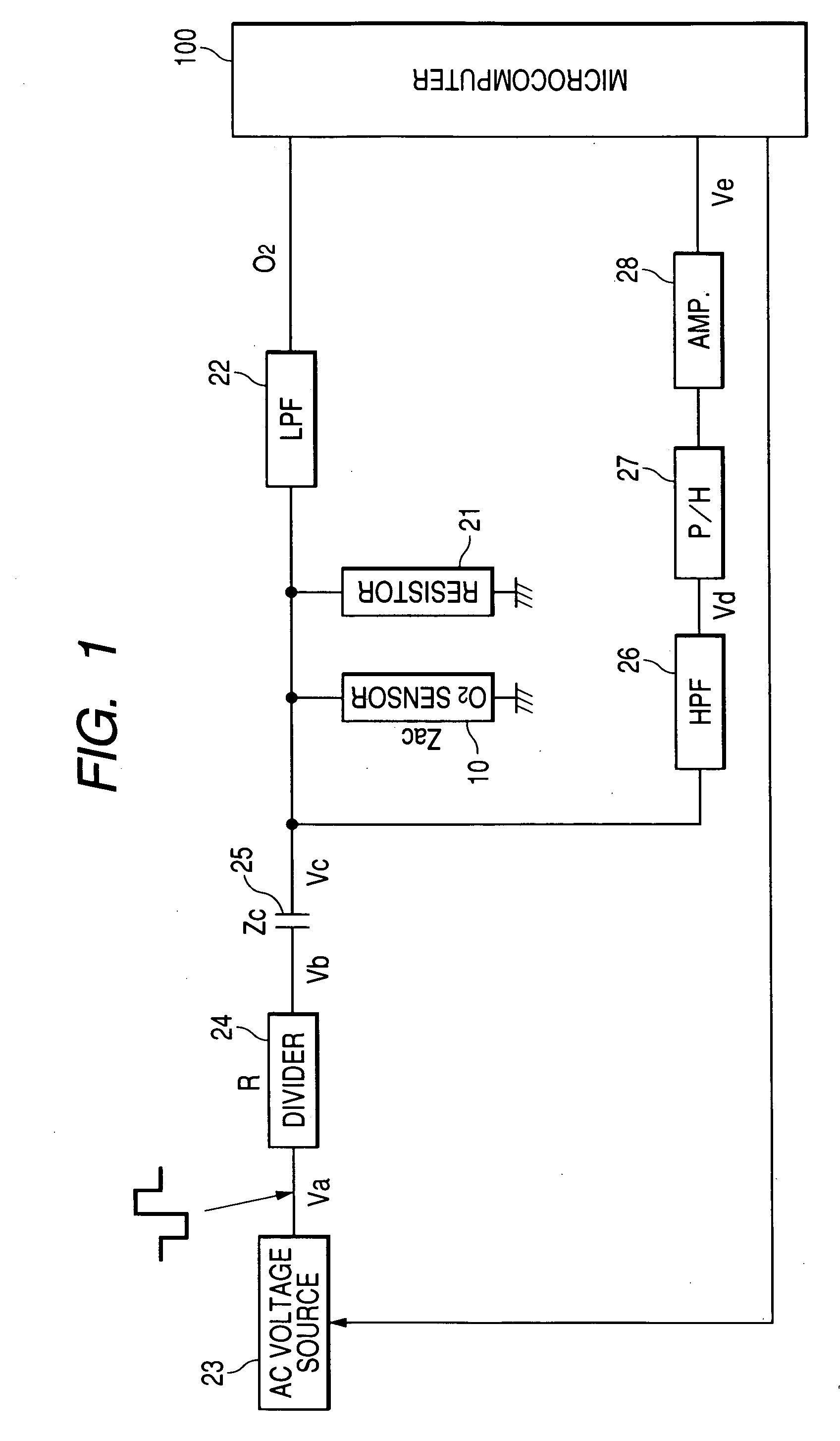
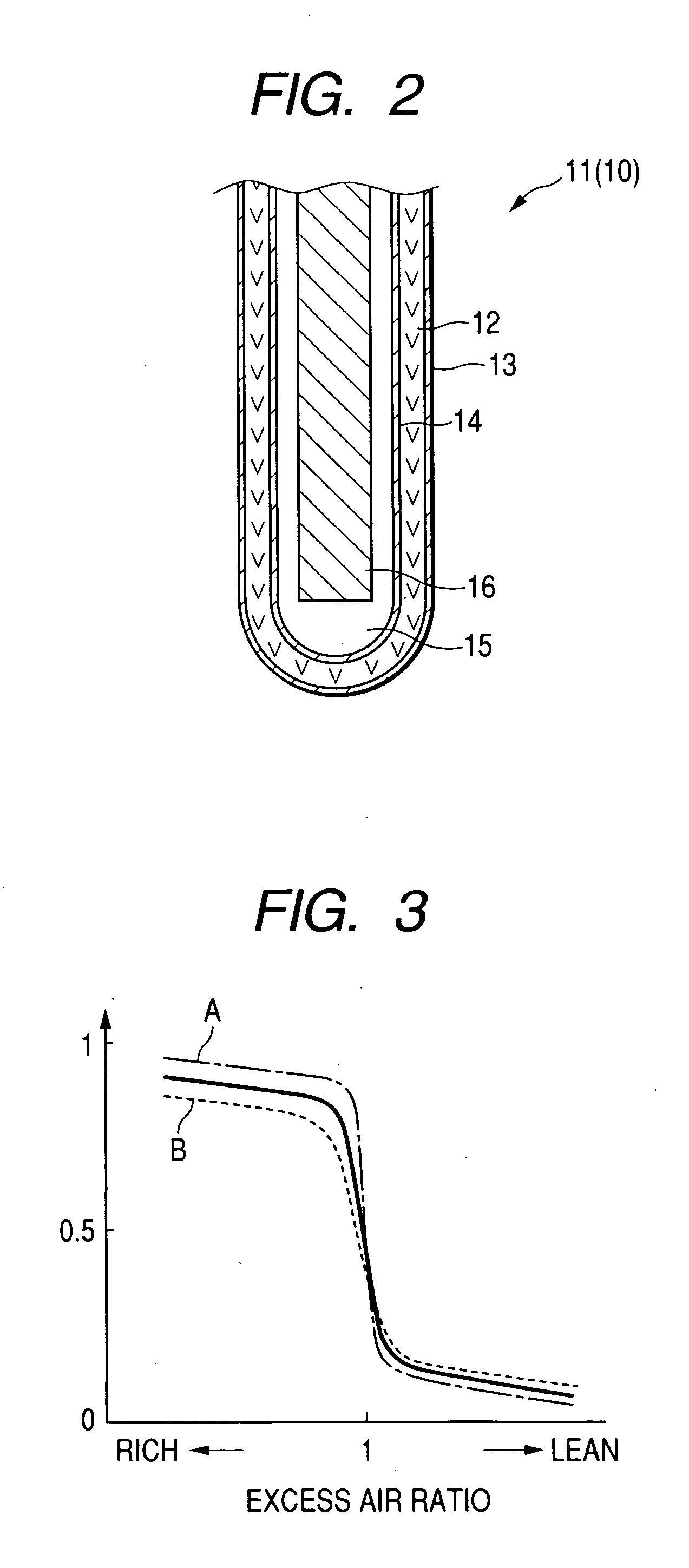
[0064] Referring now to the drawings, particularly to FIG. 1, there is shown a gas concentration measuring apparatus according to the invention which is designed to sample exhaust gasses emitted from an internal combustion engine mounted in an automobile to measure the concentration of oxygen (O2) contained in the exhaust gasses for determining an air-fuel (A / F) ratio of a mixture supplied to the engine. The determined A / F is typically used in an air-fuel ratio control system made of an engine ECU, etc. to perform stoichiometric burning control to bring the A / F ratio near the stoichiometric air-fuel ratio under feedback control. The gas concentration measuring apparatus includes an oxygen (O2) sensor 10 which has an internal structure in cross section, as illustrated in FIG. 2. The oxygen sensor 10 includes a cup-shaped sensor element 11 which is typically retained in a cylindrical housing (not shown) and covered with a protective cover assembly (not shown). In use, the oxygen senso...


PUM


Abstract

A sensor impedance measuring apparatus is provided which is designed to apply one of an alternating voltage swept in level to a positive and a negative side to a sensor element of a gas sensor such as an O2 sensor or an A/F sensor and sample the voltage developed at an end of the sensor element to determine the impedance of the sensor element. The determined impedance is, for example, used to control energization of a heater built in or affixed to the sensor element to control the activation of the sensor element for ensuring the accuracy in measuring the concentration of a gas.

Description

CROSS REFERENCE TO RELATED DOCUMENT [0001] The present application claims the benefit of Japanese Patent Application No. 2004-331017 filed on Nov. 15, 2004, Japanese Patent Application No. 2005-136456 filed on May 9, 2005, and Japanese Patent Application No. 2005-293202 filed on Oct. 6, 2005, the disclosures of which are incorporated herein by reference. BACKGROUND OF THE INVENTION [0002] 1. Technical Field of the Invention [0003] The present invention relates generally to a sensor impedance measuring apparatus designed to measure the impedance of a gas sensor for improving the measurement accuracy of the gas sensor and a gas concentration measuring apparatus equipped with such a sensor impedance measuring apparatus. [0004] 2. Background Art [0005] There are known a variety of techniques of measuring the concentration of oxygen contained in exhaust emissions of automotive internal combustion engines to use it for controlling the quantity of fuel to be injected into the engine. Such ...

Claims


Application Information

Patent Timeline
IPC IPC(8): G01N27/26
CPCG01N27/4067
Inventor NIWA, MITSUNOBUHADA, SATOSHIKUROKAWA, EIICHI
Owner DENSO CORP
Why Eureka
Try Eureka