
Method and system for split-phase line loss measurement

A measurement method and line loss technology, applied in the field of power transmission, can solve the problems of reducing the difficulty of line loss, the inability to further guide the work of anti-theft and line transformation, and the inability to accurately locate and analyze line loss, etc., to achieve the effect of reducing line loss

Inactive Publication Date: 2012-06-13
STATE GRID CHONGQING ELECTRIC POWER CO ELECTRIC POWER RES INST +1
View PDF6 Cites 8 Cited by
  • Summary
  • Abstract
  • Description
  • Claims
  • Application Information

AI Technical Summary

Problems solved by technology

[0004] In the current low-voltage line loss measurement, the single-phase ammeters in each station area cannot correctly distinguish the phases, and can only calculate the three-phase total loss, but cannot measure the individual phase line loss of the three phases, so it cannot be accurate Locating and analyzing the cause of line loss cannot further guide the work of anti-theft and line transformation, which brings difficulty in reducing line loss and cannot improve the power quality of low-voltage distribution network

Method used


Image

  • Method and system for split-phase line loss measurement
  • Method and system for split-phase line loss measurement
  • Method and system for split-phase line loss measurement

Examples


Embodiment 1

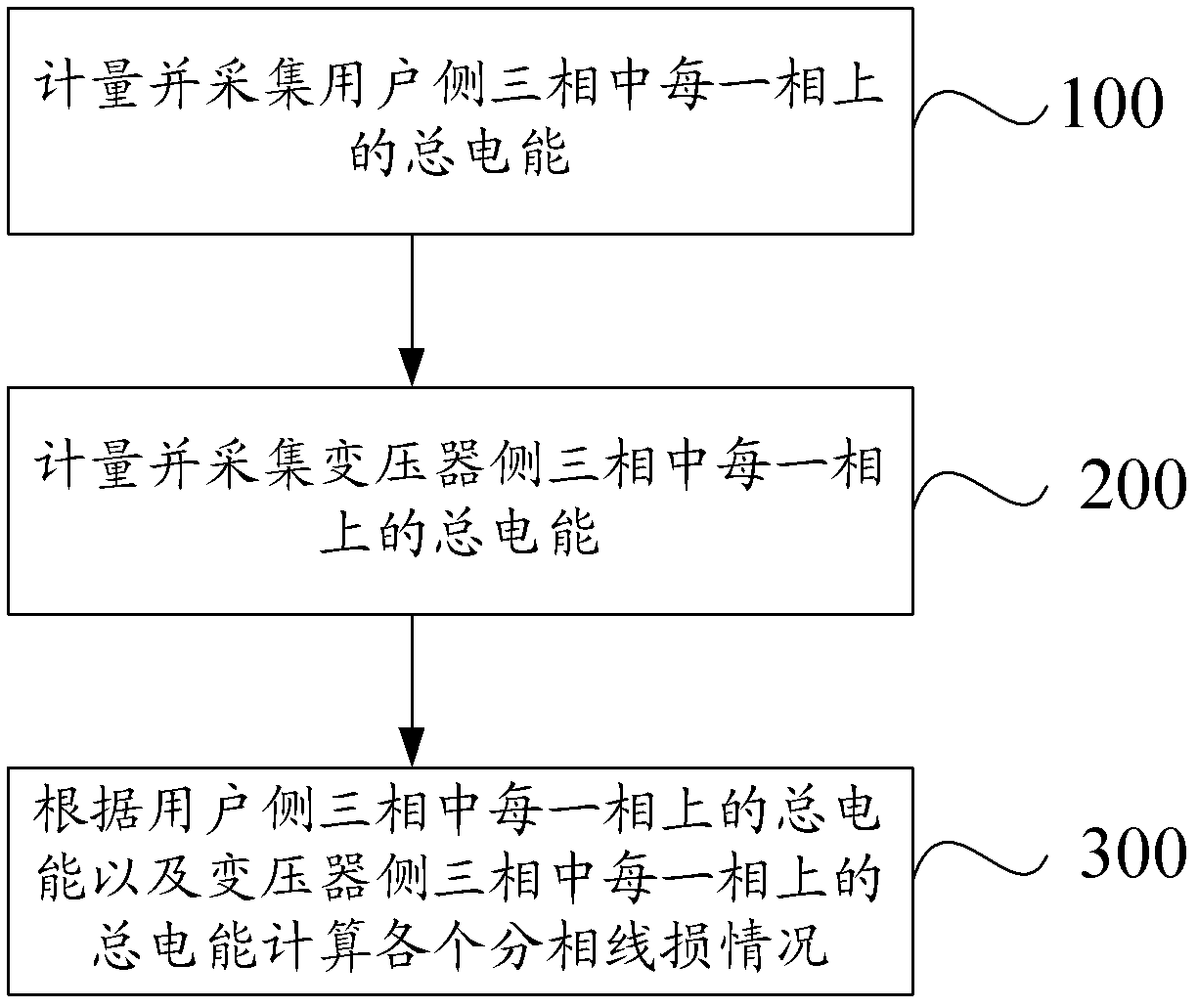
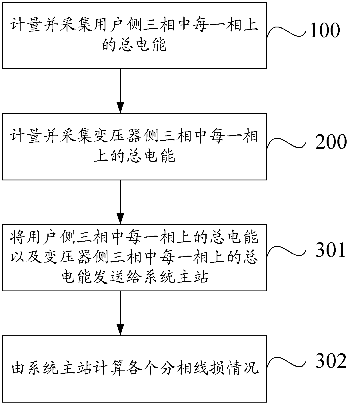
[0035] figure 1 It is a schematic flowchart of a phase-separated line loss measurement method provided in the embodiment of the present application.

[0036] Such as figure 1 As shown, the phase-splitting line loss measurement method includes the following steps:

[0037] S100: Measuring and collecting the total electric energy of each of the three phases on the user side.

[0038] In reality, each user's family is equipped with a single-phase smart meter or a three-phase smart meter, and these single-phase smart meters or multi-phase smart meters can measure the electricity consumption of each family.

[0039] For the single-phase smart meter, since it can only be distributed on one of the three phases of the power supply, in the process of electric energy measurement, as long as the phase of the single-phase smart meter is known, its positive active total electric energy is the phase. energy metering value. For the three-phase smart meter, since it can directly measure e...

Embodiment 2

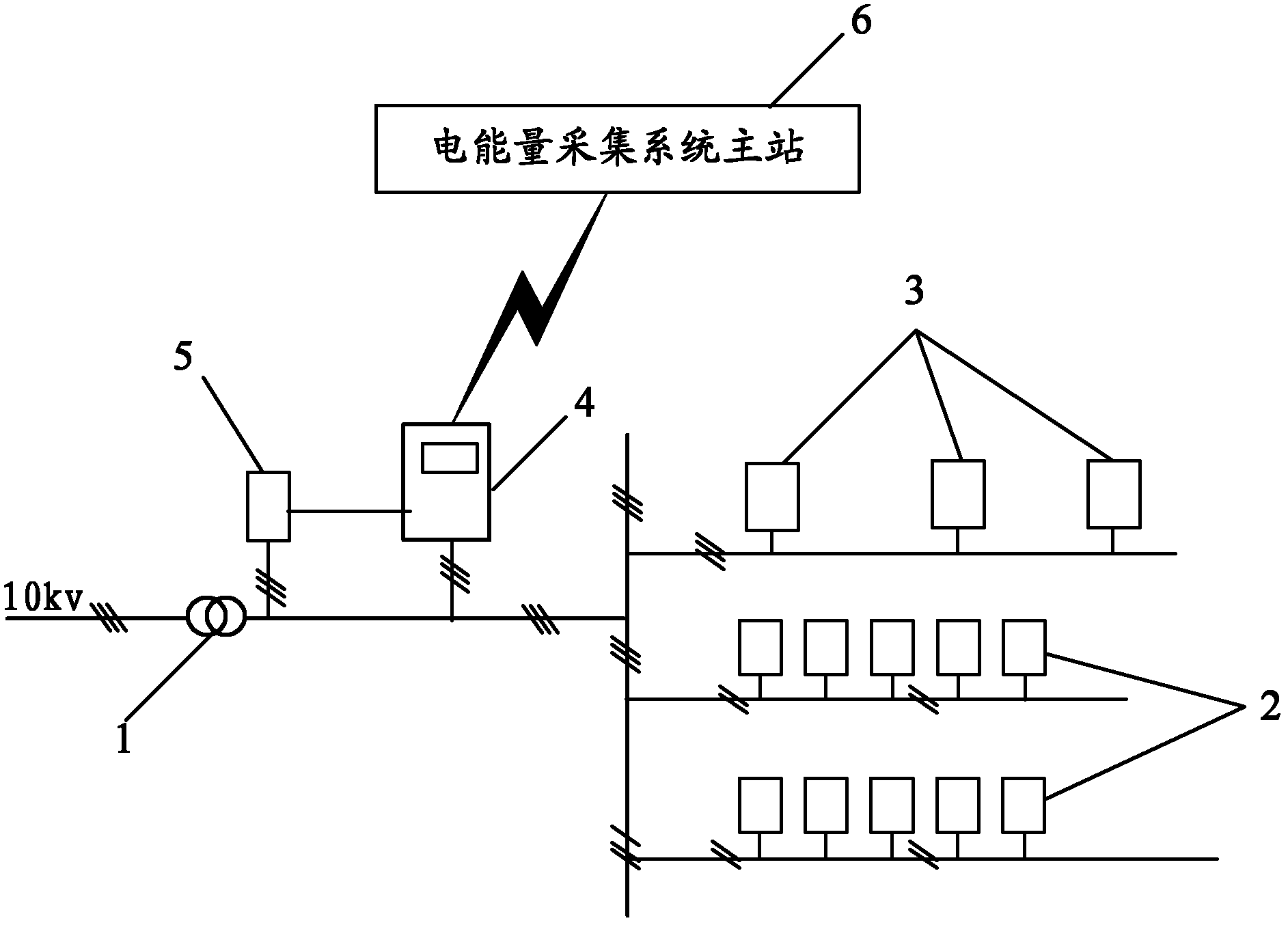
[0068] On the basis of the first embodiment above, the embodiment of the present application also provides a phase-splitting line loss measurement system, such as image 3 As shown, it is a schematic structural diagram of a phase-splitting line loss measurement system provided in the embodiment of the present application.

[0069] image 3 Among them, 1 is the transformer in the station area. Such as image 3 As shown, the phase-splitting line loss measurement system includes: several single-phase electric energy meters 2, several three-phase electric energy meters 3, concentrators 4, three-phase assessment tables 5 and a system master station 6, wherein:

[0070] Several single-phase electric energy meters 2 and several three-phase electric energy meters 3 are used to measure the total electric energy on each phase of the user side;

[0071] The concentrator 4 is used to collect the total electric energy on each phase of the user side measured by several single-phase smart...


PUM


Abstract

The invention discloses a method and system for split-phase line loss measurement. The method for the split-phase line loss measurement comprises the following steps of: calculating and acquiring total electric energy of each phase of three phases on a user side; calculating and acquiring total electric energy of each phase of the three phases on a transformer side; and respectively calculating a line loss situation of each split phase according to the acquired total electric energy of each phase of the three phases on the user side and the acquired total electric energy of each phase of the three phases on the transformer side. According to the method for the split-phase line loss measurement, disclosed by the invention, the acquisition of split-phase electric energy of a user can be realized, and the line loss situation of each split phase can be measured, so that requirements on split-phase line loss management are met, therefore the purpose of guiding line loss reduction is achieved.

Description

technical field [0001] The present application relates to the technical field of electric power transmission, in particular to a method and system for measuring phase-separated line loss. Background technique [0002] Distribution network generally refers to power lines of 10 kV and below, as well as equipment and facilities such as power transformation, power distribution, protection, and control in the line, and is an important part of the power system that directly supplies power to end users. In the process of power supply, the distribution network will inevitably produce energy loss, which is called line loss. Line loss is generally divided into technical line loss and management line loss. Technical line loss is the capacity loss caused by the technical parameters of the equipment and the line itself (such as copper loss and iron loss of the transformer, heat generated by voltage drop caused by line resistance and contact resistance) loss, etc.), management line loss ...

Claims


Application Information

Patent Timeline
Patent Type & Authority Applications(China)
IPC IPC(8): G01R31/00G01R11/00G08C17/02
Inventor 孙洪亮侯兴哲周孔均欧习洋郑可冯凌刘永相
Owner STATE GRID CHONGQING ELECTRIC POWER CO ELECTRIC POWER RES INST
Learn More