
Artificial blood vessel

An artificial blood vessel and bypass tube technology, applied in the field of artificial blood vessels, can solve the problems of blocking blood flow, hypoxia and necrosis, organ ischemia, etc., and achieve the effect of improving the success rate, reducing pain, and avoiding damage

Inactive Publication Date: 2014-04-16
THE THIRD AFFILIATED HOSPITAL OF THIRD MILITARY MEDICAL UNIV OF PLA
View PDF5 Cites 0 Cited by
  • Summary
  • Abstract
  • Description
  • Claims
  • Application Information

AI Technical Summary

Problems solved by technology

At present, there are many types of artificial blood vessels, but it is required to block the blood flow of the own blood vessels that are anastomosed with the artificial blood vessels before anastomosing the artificial blood vessels with human blood vessels, otherwise the operation cannot be performed
However, blocking blood flow has ischemia and hypoxia problems for the organs dominated by the arteries: for organs with strong tolerance to ischemia and hypoxia, such as limbs, short-term ischemia may not cause obvious Complications: For organs that are more sensitive to ischemia and hypoxia, such as the brain for more than 6 minutes, and liver, kidney, and small intestine for more than 20 minutes, their functions can be affected, and severe cases can lead to organ ischemia and hypoxia necrosis
Therefore, the use of ordinary artificial blood vessels for vascular anastomosis, because of the limitation of operation time, the operation is difficult to carry out smoothly and the control vessels will cause ischemia, hypoxia and necrosis of important organs in the case of a long period of interruption during the operation. Posterior complications directly affect the success rate of surgery

Method used


Image

  • Artificial blood vessel
  • Artificial blood vessel
  • Artificial blood vessel

Examples


Embodiment Construction

[0015] Below in conjunction with accompanying drawing and embodiment the present invention will be further described:

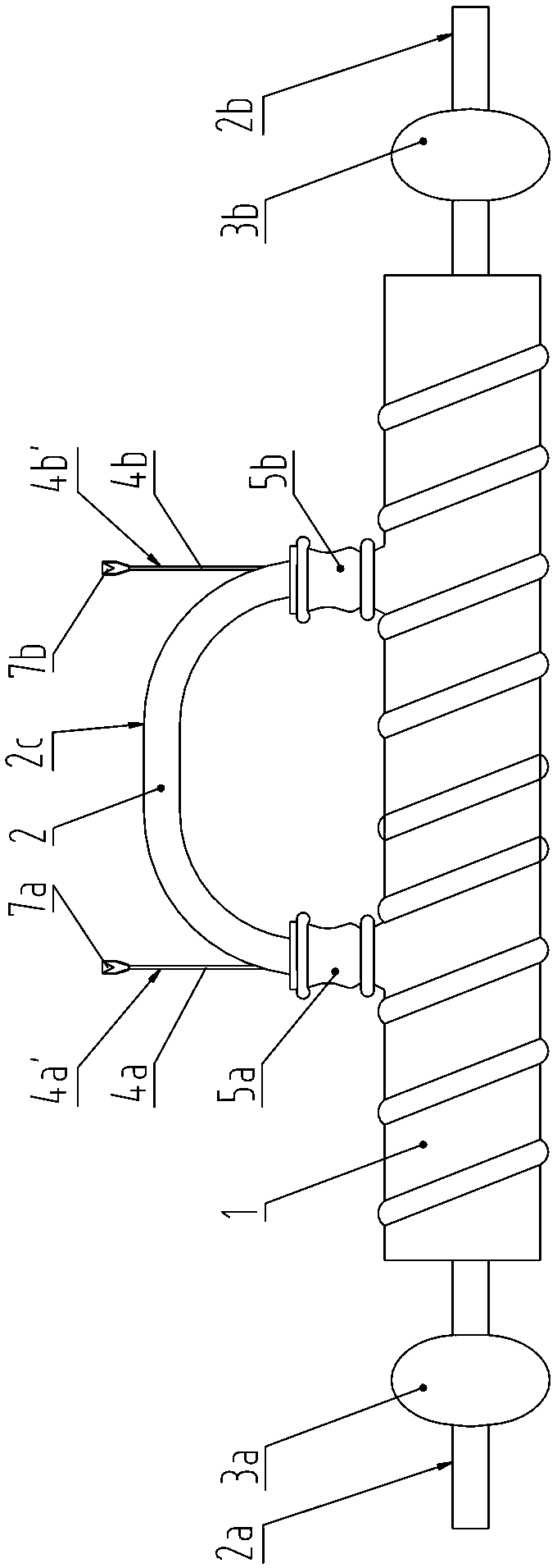
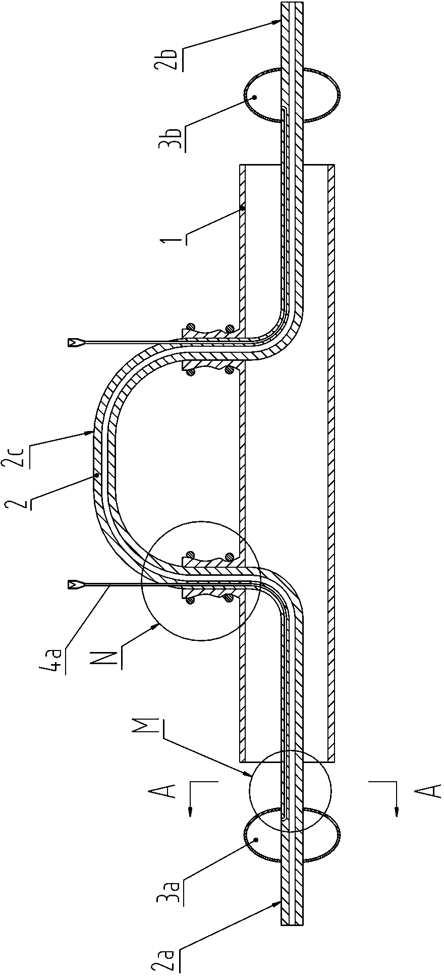
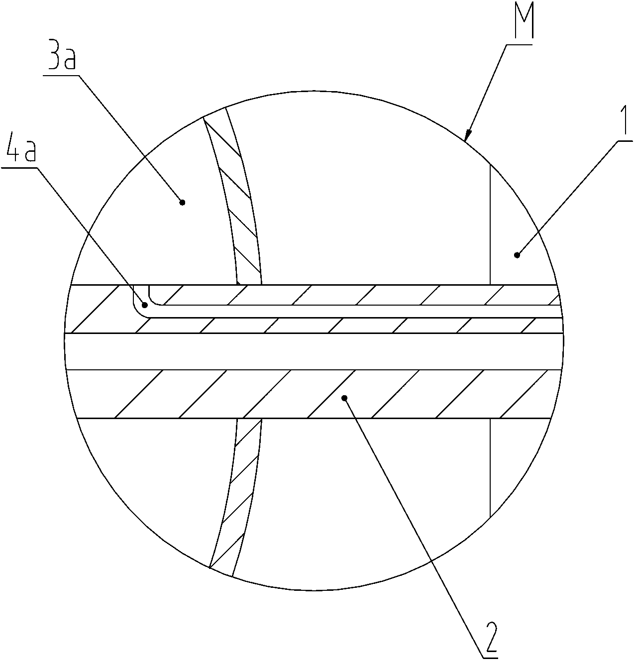
[0016] see Figure 1 to Figure 5 , an artificial blood vessel, comprising an artificial blood vessel body 1, a shunt tube 2 made of silicone tube, two airbags and two inflation tubes, the two airbags are respectively a left airbag 3a and a right airbag 3b, and the two inflation tubes They are the left inflation tube 4a and the right inflation tube 4b respectively. Wherein, the side wall of the artificial blood vessel body 1 is provided with a first perforation and a second perforation, the outer edge of the first perforation has a first skirt 5a extending to the outside of the artificial blood vessel body, and the outer edge of the second perforation has a skirt 5a extending toward the outside of the artificial blood vessel body. The second skirt 5b extending outside the artificial blood vessel body, the first skirt 5a, the second skirt 5b and the artificial...


PUM


Abstract

The invention provides an artificial blood vessel which comprises an artificial blood vessel main body, a shunt vessel, two air bags and two air filled vessels, wherein the side wall of the artificial blood vessel main body is provided with two through holes, each through hole is provided with an outward extending skirt edge, and each skirt edge is provided with a tightening line; both ends of the shunt vessel respectively pass through the artificial blood vessel main body from the two through holes and the skirt edges and extends our of both ends of the artificial blood vessel main body, and each extension section of both ends of the shunt vessel passes through one air bag and is hermetically connected with the air bag; and both air filled vessels are arranged in the vessel wall of the shunt vessel, one end of each air filled vessel extends out from the middle section of the shunt vessel, and the other end is communicated with one air bag. Surgeries can be performed without blocking the blood flow in the human blood vessel by using the shunt vessel and the two air bags, the anastomosis between the artificial blood vessel and the human blood vessel is completed, organ ischemia is avoided, the success ratio of surgeries and the convenience of surgery operations are increased, and the pain of patients in surgeries is relieved.

Description

technical field [0001] The invention relates to a surgical implant of a medical device, in particular to an artificial blood vessel. Background technique [0002] Arterial vascular injury, arterial vascular disease, or organ autotransplantation often require artificial blood vessels to replace their own blood vessels. At present, there are many types of artificial blood vessels, but they are required to block the blood flow of the self-vascularized blood vessels anastomosed with the artificial blood vessels before performing anastomosis of the artificial blood vessels with the human blood vessels, otherwise the operation cannot be performed. However, blocking blood flow has ischemia and hypoxia problems for the organs dominated by the arteries: for organs with strong tolerance to ischemia and hypoxia, such as limbs, short-term ischemia may not cause obvious Complications: For organs that are more sensitive to ischemia and hypoxia, such as the brain for more than 6 minutes, ...

Claims


Application Information

Patent Timeline
Patent Type & Authority Patents(China)
IPC IPC(8): A61F2/06
Inventor 文亚渊
Owner THE THIRD AFFILIATED HOSPITAL OF THIRD MILITARY MEDICAL UNIV OF PLA
Learn More