Die insert fixing structure

A technology for fixing structures and inserts, which is applied to forming tools, manufacturing tools, metal processing equipment, etc., can solve problems such as insert installation problems, and achieve the effect of increasing adjustment space and improving flexibility.

Active Publication Date: 2012-06-20
CHERY AUTOMOBILE CO LTD
View PDF6 Cites 15 Cited by
  • Summary
  • Abstract
  • Description
  • Claims
  • Application Information

AI Technical Summary

Problems solved by technology

[0003] The purpose of this invention is to propose a mold insert fixing str

Method used


Image

  • Die insert fixing structure
  • Die insert fixing structure
  • Die insert fixing structure

Examples


Embodiment 1

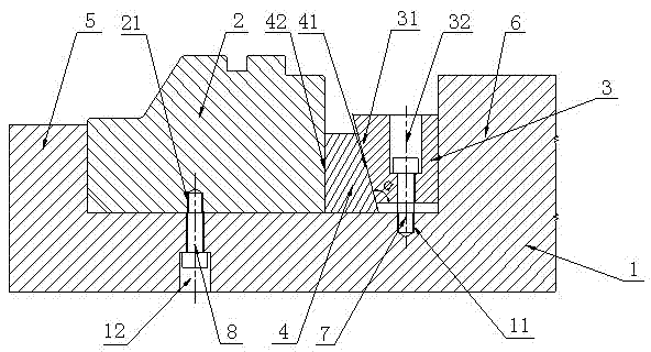
[0019] Such as figure 2 As shown, the mold insert fixing structure of this embodiment includes a mold base 1, an insert 2, a first wedge 3 and a second wedge 4 with a flat bottom surface; the mold base 1 is provided with a protrusion for blocking the movement of the insert 2 The first stopper 5 and the protruding second stopper 6 for blocking the movement of the first wedge 3, the first stopper 5 and the second stopper 6 are respectively arranged on both sides of the predetermined installation position of the insert 2; The mold base 1 is provided with a first threaded hole 11 between the second stopper 6 and the predetermined installation position of the insert 2; the first wedge 3 is provided with a first inclined side 31 with an inclination angle α greater than 90° and is used for matching with the The first threaded hole 11 cooperates with the through hole 32 for installing the bolt in the first threaded hole 11, and the side 33 opposite to the first inclined side 31 of th...

Embodiment 2

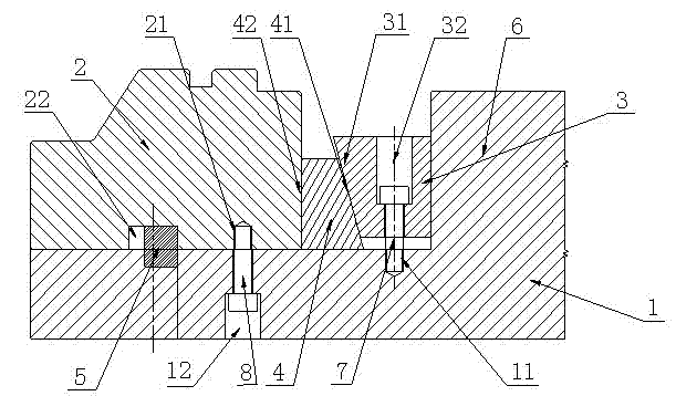
[0023] Such as image 3 As shown, the difference from Embodiment 1 is that the first stopper 5 of this embodiment is arranged at the predetermined installation position of the insert 2 , and the bottom of the insert 2 is provided with a recess 22 for cooperating with the first stopper 5 . This method is suitable for the case where the predetermined installation position of the insert 2 is located at the edge of the mold base 1 , and the movement of the insert 2 can be prevented by the cooperation of the first stopper 5 and the recess 22 of the insert. The length of the recess 22 is greater than the length of the first stopper 5 to facilitate the adjustment of the position of the insert 2 within a certain range.


PUM

PropertyMeasurementUnit
Inclinationaaaaaaaaaa

Abstract

The invention provides a die insert fixing structure, aiming to solve the problems in insert mounting due to heat treatment. The die insert fixing structure comprises a die holder, an insert, a first wedge and a second wedge. The die holder is provided with a first stopper used for preventing the insert from moving and a second stopper used for preventing the first wedge from moving, both the first stopper and the second stopper are protruded, and a first thread hole is arranged between the second stopper and a preset mounting position of the insert on the die holder. The first wedge is provided with a first oblique side and a through hole, wherein the through hole is matched with the first thread hole so that a bolt can be mounted in the first thread hole. The second wedge is provided with a second oblique side and a first mounting side, wherein the second oblique side is matched with the first oblique side, and the first mounting side is used for matching with one side of the insert. By matching between the stoppers and the wedges, the insert can be clamped and fixed, the position of the insert can be adjusted within a small range during the fixing process, and accordingly the problem in mounting of the insert which deforms due to heat treatment is solved. The die insert fixing structure has higher practicability.

Description

technical field [0001] The invention belongs to the technical field of mechanical manufacturing, and in particular relates to a mold insert fixing structure. Background technique [0002] In recent years, with the development of the domestic machinery manufacturing industry, the domestic mold industry has a certain scale and technology accumulation, and has been widely used. Taking the automobile industry as an example, cold stamping dies are the main tool for the production of automobile body-in-white parts. The use of dies can ensure the consistency and production efficiency of stamping parts, which is irreplaceable by other production tools. but if figure 1 As shown, the fixing structure of the mold insert is usually to use bolts (4) to fix the insert (1) on the mold seat (3). This structure has the following problems: 1. The mold insert (1) is generally Heat treatment is required to ensure its strength and reliability, but the insert (1) will undergo certain deformatio...

Claims


Application Information

Patent Timeline
IPC IPC(8): B21D37/10
Inventor 唐东胜
Owner CHERY AUTOMOBILE CO LTD
Why Eureka
Try Eureka