Impeller for washing machine and washing machine using impeller

A technology of washing machine and pulsator, applied in the field of washing machine, which can solve the problems such as the load is not easy to turn over, the amount of clothing slippage is small, and the clothes are not easy to turn over, so as to achieve the effect of low cost, improved washing rate, and easy turning over

Active Publication Date: 2012-06-20
QINGDAO HAIER WASHING MASCH CO LTD
View PDF4 Cites 15 Cited by
  • Summary
  • Abstract
  • Description
  • Claims
  • Application Information

AI Technical Summary

Problems solved by technology

The traditional pulsator structure is provided with multiple convex ribs on the pulsator. The shape of the ribs is generally narrow at the top and wide at the bottom, that is, it is narrow near the center of the pulsator and wide near the edge of the pulsator. The slope of the shape is relatively large. The pulsator of this structure has a small slippage of the clothes during the washing process, which is not conducive to the turning of the clothes, and only relies on the rotation of a single pulsator to drive the water flow. Wash clothes efficiently, but when the load is large, the load is not easy to turn over, easy to entangle, the washing effect is weak, and the washing rate is low

Method used


Image

  • Impeller for washing machine and washing machine using impeller
  • Impeller for washing machine and washing machine using impeller
  • Impeller for washing machine and washing machine using impeller

Examples


Embodiment 1

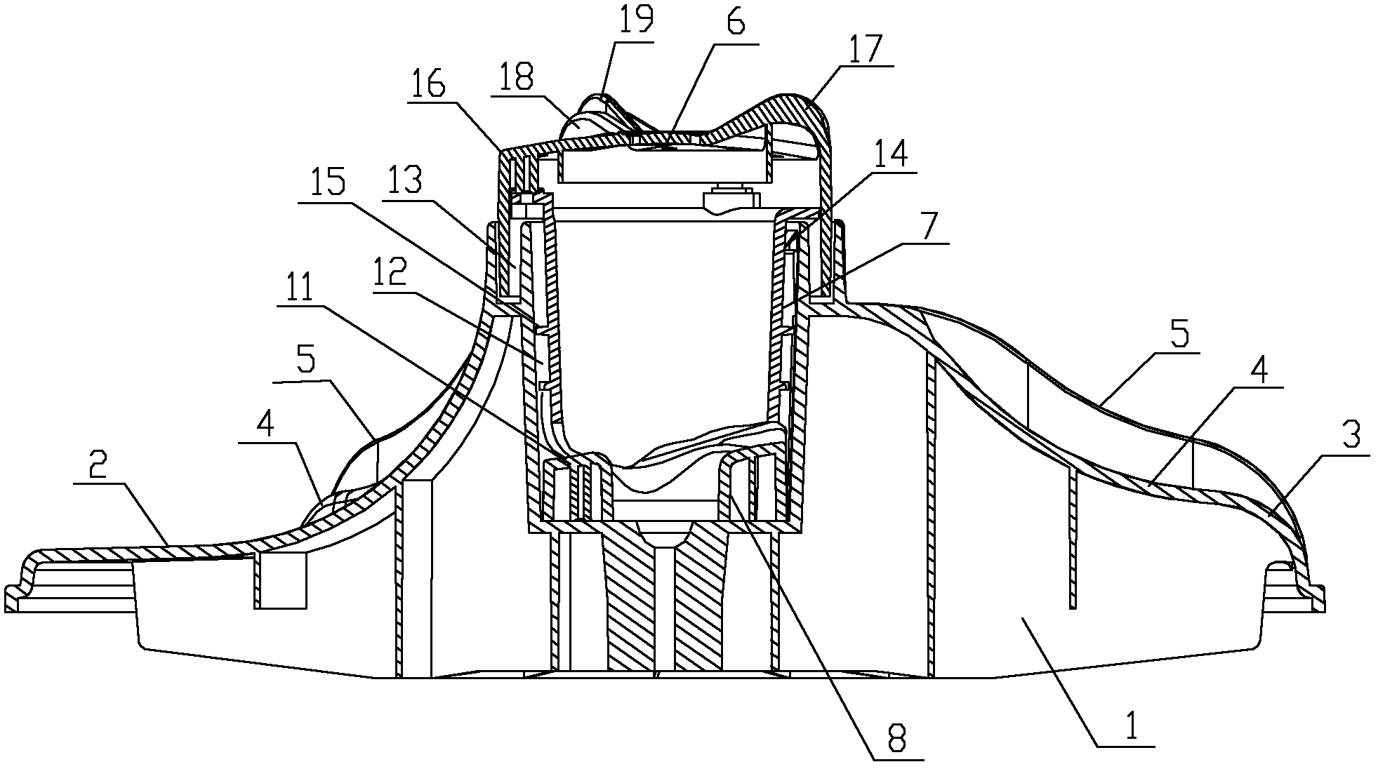
[0031] The pulsator washing machine commonly used in family life at present comprises a housing (not shown in the figure), on which a control panel and a door for taking and placing clothes are arranged on the surface of the housing, and a water tank for holding water is arranged in the housing. An outer cylinder (not shown in the figure) and an inner cylinder (not shown in the figure) for washing, wherein the outer cylinder is fixed and does not rotate, the inner cylinder is arranged on the inner side of the outer cylinder, and the inner cylinder is driven by a driving device (in the figure not shown) to drive the rotation, the wall of the inner cylinder has several openings for the passage of washing water, the bottom of the inner cylinder is provided with a pulsator, and the pulsator is driven by a driving device. A water inlet is arranged on the upper part of the outer cylinder for water intake in the washing and rinsing process, and a water outlet is arranged on the lower ...

Embodiment 2

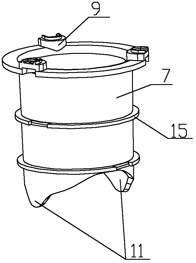
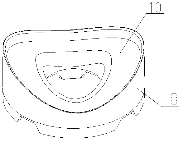
[0046] The difference from Embodiment 1 is that, as Figure 5 As shown, the top of the sliding chassis 8 has a sliding slope 20 . Such as Figure 4 As shown, there is a downward protruding cam 11 at the bottom of the impact bar 7, and the bottoms of the two cams 11 are in sliding contact with the sliding slope 20. When the impact bar 7 or the sliding chassis 8 rotates, the cam at the bottom of the impact bar 7 11 slides along the sliding slope 20, and at the same time, the impact rod 7 makes vertical reciprocating motion up and down under the action of the sliding slope 20, and then drives the small wave wheel 6 to make vertical reciprocating motion up and down.


PUM


Abstract

The invention relates to an impeller for a washing machine and a washing machine using the impeller. The impeller for the washing machine comprises a big impeller which is arranged on the bottom of an inner cylinder of the washing machine, wherein the big impeller is connected with a driving device of the washing machine; a small impeller is arranged in the center of the big impeller; and the small impeller rotates and performs up-down vertical reciprocating motion relative to the big impeller through a linking mechanism. When more washing loads are washed, the small impeller can achieve an auxiliary washing effect, so that the cleaning rate is improved. The small impeller can also perform up-down vertical reciprocating motion when rotating so as to scatter load cloth, so that the problem about the tangling when the loading capacity is high is well solved, and the cleaning effect when the loading capacity is high is improved; meanwhile, the turning effect of the loads in the washing process is remarkably improved.

Description

technical field [0001] The invention relates to a washing machine pulsator and a washing machine using the pulsator, belonging to the technical field of washing machines. Background technique [0002] The washing machine has become one of the necessary household appliances in every family. The washing machine has developed from the original single function to the diversification, but no matter what kind of washing machine, its cleaning rate and anti-winding performance have always been important to measure the performance of the washing machine. index. [0003] For the currently commonly used pulsator washing machine, it mainly includes a shell, an outer cylinder is arranged in the casing, an inner cylinder is arranged in the outer cylinder, and a pulsator is arranged at the bottom of the inner cylinder, and the driving device is connected with the pulsator through a transmission mechanism. , and drives the pulsator to rotate. This kind of washing machine uses the periodic...

Claims


Application Information

Patent Timeline
Patent Type & Authority Applications(China)
IPC IPC(8): D06F17/06D06F17/08D06F17/10
Inventor 张涛张刚金田云龚孟虎李峰周春霞
Owner QINGDAO HAIER WASHING MASCH CO LTD
Why Eureka
Try Eureka