
Ground moving target detection and parameter estimation method

A technology for ground moving target and parameter estimation, which is applied in the field of synthetic aperture radar signal processing and can solve problems such as inability to detect moving targets, blind speed phenomenon, and distance velocity ambiguity.

Inactive Publication Date: 2012-06-20
NAT UNIV OF DEFENSE TECH
View PDF2 Cites 30 Cited by
  • Summary
  • Abstract
  • Description
  • Claims
  • Application Information

AI Technical Summary

Problems solved by technology

Since the phase Δφ of the moving target changes from the distance to the velocity v y It is determined that this type of method has two shortcomings: (1) Since Δφ takes 2π as a period, even if v y is not zero, its corresponding Δφ may also be zero, and blind speed phenomenon occurs when detecting the target; in addition, different v y The corresponding Δφ may be the same, and there will be a range-velocity ambiguity problem when estimating parameters; (2) Since the phase Δφ is only related to v y Related, so this kind of method can only detect and estimate the moving target whose range velocity is not zero, but cannot detect the moving target whose range velocity is zero but the azimuth velocity is not zero, nor can it estimate the azimuth velocity of the target
The UWB SAR system has a long wavelength and requires a long baseline. Due to the limitation of the antenna size and platform size, it is very difficult to install four receiving antennas on the carrier aircraft to form an effective baseline. At the same time, the excessive number of antennas increases the hardware and storage burden. The use of multi-frequency or multi-trigger schemes also increases the complexity of the system

Method used


Image

  • Ground moving target detection and parameter estimation method
  • Ground moving target detection and parameter estimation method
  • Ground moving target detection and parameter estimation method

Examples


Embodiment Construction

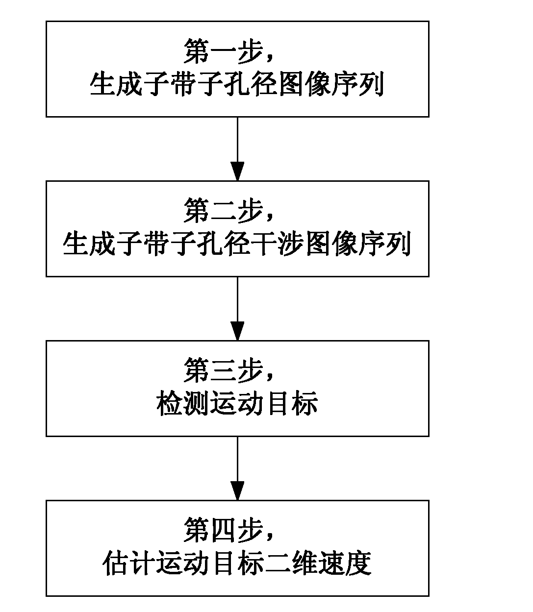
[0049] figure 1 It is the flow chart of the realization of the present invention. The whole process is mainly divided into four steps: the first step is to generate sub-band sub-aperture image sequence, the second step to generate sub-band sub-aperture interference image sequence, the third step to detect moving objects, and the fourth step to estimate the radial velocity and two-dimensional velocity of moving objects.

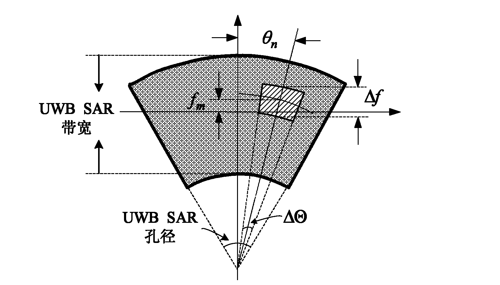
[0050] The first step is to pay attention to the selection of sub-band bandwidth, sub-aperture accumulation angle, sub-band center frequency, and sub-aperture viewing angle in the process of sub-band sub-aperture image generation. The relationship between resolution and defocusing of moving objects needs to be considered. If the target speed is high, a lower resolution is required, and the sub-band bandwidth and sub-aperture accumulation angle can be smaller; if the target speed is low, a higher resolution is required, and the sub-band bandwidth and sub-apert...


PUM


Abstract

The invention provides a ground moving target detection and parameter estimation method. The technical scheme realizes the moving target detection and two-dimensional velocity estimation by combining with an interference image sequence with multiple sub-bands and sub-apertures on the basis of a three-way ultra-wide bandwidth (UWB) synthetic aperture radar (SAR) image. The specific steps of the method are as follows: 1, generating a sub-band sub-aperture image sequence; 2, generating a sub-band sub-aperture interference image sequence; 3, detecting the moving target; and 4, estimating the two-dimensional velocity of the moving target. By using the ground moving target indication and parameter estimation method provided by the invention, the moving target and a static target can be distinguished on an imaging position and a phase position; the radial velocity of the moving target can be estimated clearly; and the azimuth speed and distance speed can also be estimated.

Description

technical field [0001] The invention belongs to the technical field of synthetic aperture radar signal processing, and relates to a ground moving target detection and parameter estimation method, in particular using three-channel UWB SAR (Ultra Wide-band Synthetic Aperture Radar, ultra-wideband synthetic aperture radar) images to detect ground moving targets Detection and parameter estimation methods. Background technique [0002] UWB SAR system is an imaging radar with the ability of leaf cluster penetration and can simultaneously obtain two-dimensional high resolution. The multi-channel UWB SAR system is used to realize the GMTI (Ground Moving Target Indication, ground moving target indication) function, which can conduct reconnaissance, surveillance and imaging of stationary and moving targets in a wide open flat or leaf-covered area. On UWB SAR images, the phase difference between moving and stationary targets is used to detect moving targets. Due to the long coherent p...

Claims


Application Information

Patent Timeline
IPC IPC(8): G01S13/90G01S7/41
Inventor 周智敏黄晓涛周红雷鹏正朱国富黎向阳李悦丽
Owner NAT UNIV OF DEFENSE TECH
Learn More