Staring infrared imaging forest-fire prevention alarming system with wide field of view

An infrared imaging and forest fire prevention technology, applied in the optical field, can solve the problems of inaccurate positioning of the fire point, limited stability and precision, and limited monitoring coverage, so as to avoid full emission, prevent missing alarms, and improve the axis Effect of Outer Point Illumination

Inactive Publication Date: 2012-06-20
CHANGCHUN INST OF OPTICS FINE MECHANICS & PHYSICS CHINESE ACAD OF SCI
View PDF4 Cites 12 Cited by
  • Summary
  • Abstract
  • Description
  • Claims
  • Application Information

AI Technical Summary

Problems solved by technology

At present, the infrared optical system used in forest fire prevention and other fields can only monitor a small area below 30 degrees, and the optical system can only acquire images; it needs to rely on a mechanical scanning mechanism to realize the search; the position of the fire point cannot be accurately located; stability and Accuracy is limited by the mechanical structure
Under normal circumstances, the monitoring range of the forest area is relatively large, and each monitoring point needs to be responsible for 360-degree all-round visual coverage. If the monitoring coverage of the conventional system is limited, multiple systems need to work together

Method used


Image

  • Staring infrared imaging forest-fire prevention alarming system with wide field of view
  • Staring infrared imaging forest-fire prevention alarming system with wide field of view
  • Staring infrared imaging forest-fire prevention alarming system with wide field of view

Examples


Embodiment 1

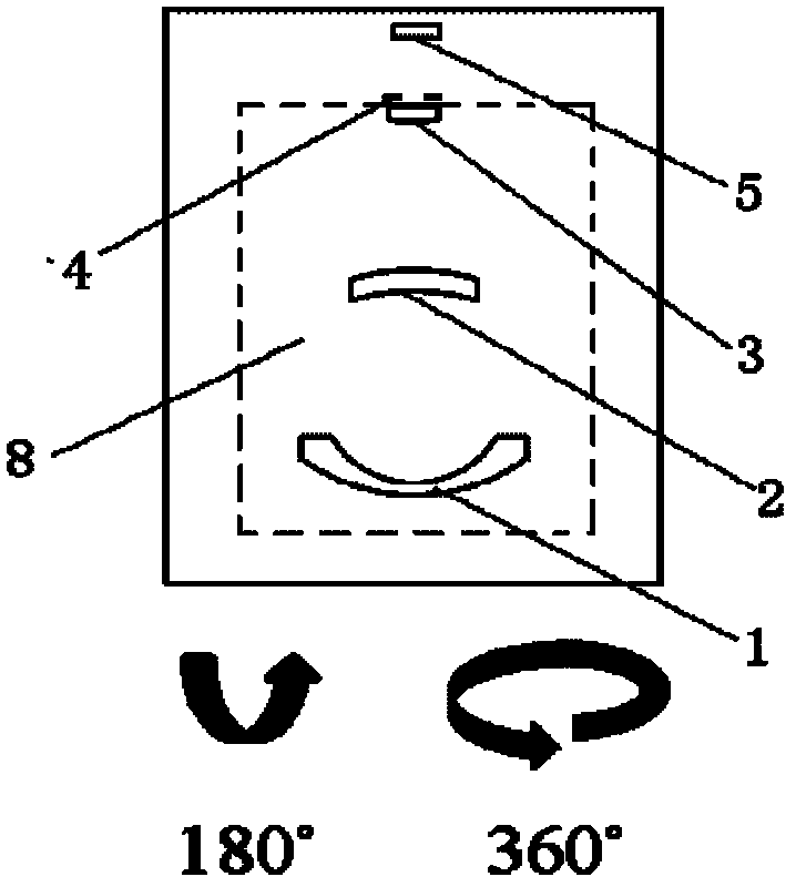
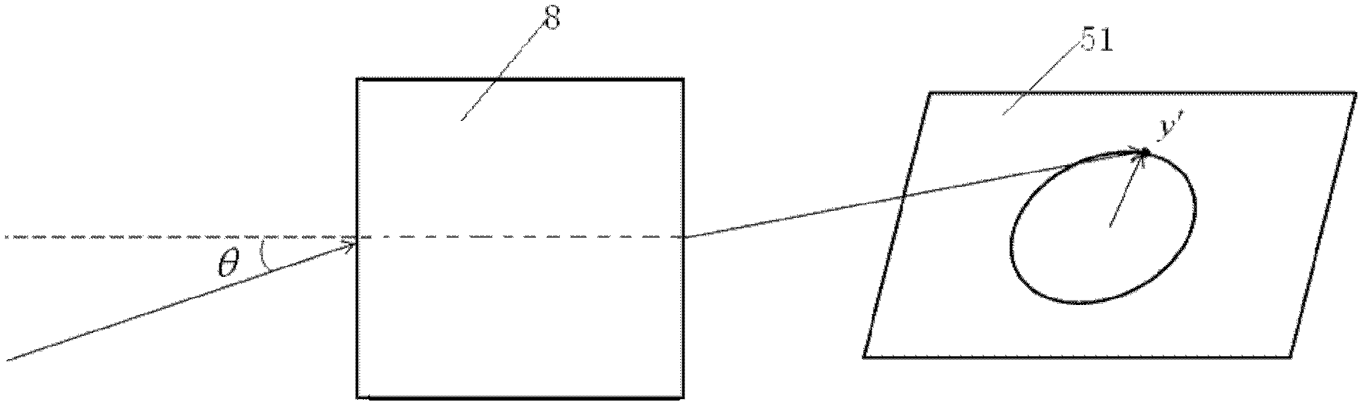
[0032] Such as image 3 As shown, the infrared imaging optical lens 8 includes a meniscus negative lens 1 , first and second positive lenses 2 and 3 , a cold diaphragm 4 and an infrared cooling detector 5 . The front surface 11 of the meniscus negative lens 1, the front surface 21 and the back surface 22 of the first positive lens, and the front surface 31 and the back surface 32 of the second positive lens are spherical; the back surface 12 of the meniscus negative lens 1 is Even-order aspheric surface, and add diffraction structure on the even-order aspheric surface. The position of the image point and the spatial orientation information of the object conform to the y′=fθ object-image relationship, and the object image points correspond one by one, and the image distance formed by the rays of the same angle of view on the focal plane array 51 is radial to the center of the focal plane array. equal distance. Where y' is the image height of the image formed by the object on ...

Embodiment 2

[0039] Such as Figure 4As shown, the infrared imaging optical lens 8 includes a meniscus negative lens 1 , first and second positive lenses 2 and 3 , a cold diaphragm 4 and an infrared cooling detector 5 . The front surface 11 of meniscus negative lens 1, the back surface 22 of the first positive lens and the front surface 31 of the second positive lens are spherical; The back surface 12 of meniscus negative lens 1, the front surface 21 of the first positive lens and the second The rear surfaces 32 of the two positive lenses are even-order aspheric surfaces.

[0040] The light passes through the meniscus negative lens 1, the first positive lens 2, and the second positive lens 3, and is finally imaged on the focal plane array 51 of the infrared cooling detector. The position of the imaging image point and the orientation information of the object space conform to the relationship of y′=fθ object image , where y′ is the image height of the image formed by the object on the inf...

Embodiment 3

[0048] Such as Figure 4 as shown in Figure 4 As shown, the infrared imaging optical lens 8 includes a meniscus negative lens 1 , first and second positive lenses 2 and 3 , a cold diaphragm 4 and an infrared cooling detector 5 . The front surface 11 of meniscus negative lens 1, the back surface 22 of the first positive lens and the front surface 31 of the second positive lens are spherical; The back surface 12 of meniscus negative lens 1, the front surface 21 of the first positive lens and the second The rear surfaces 32 of the two positive lenses are even-order aspheric surfaces. And a diffractive structure is added to the back surface 12 of the meniscus negative lens 1 .

[0049] The rear surface 12 of the meniscus negative lens 1, the second positive lens front surface 21, and the third positive lens rear surface 32 are selected from rotationally symmetrical even-order aspheric surfaces (even asphere), and the description equation is:

[0050] z ...


PUM


Abstract

The invention relates to a staring infrared imaging forest-fire prevention alarming system with a wide field of view. The system comprises an infrared imaging optical lens and an infrared refrigeration detector. Light rays are imaged on a focal plane array of the infrared refrigeration detector through the infrared imaging optical lens. The infrared imaging optical lens adopts a retrofocus structure. The imaging position of the infrared imaging optical lens and the spatial orientation information of an object form the object-image relationship of y'=fTheta, wherein y' is the image height of an image of the object on the focal plane array of the infrared refrigeration detector, f is the focal length of the infrared imaging optical lens, and Theta is an angle of field of view. The system adopts staring imaging, and a mechanical scanning structure is eliminated, so that the stability of the system is enhanced; and the system has the ultra-wide field of view of 180 degrees, and can realize the real-time imaging of all peripheral zones without any dead zone, so that the condition of false alarm can be effectively prevented, and a plurality of fire points can be discovered and monitoredat the same time.

Description

technical field [0001] The invention belongs to the field of optical technology, and relates to a staring infrared imaging optical system with a large field of view, which is used for early warning of forest fire prevention. Background technique [0002] my country's forest resources cover a large area. Today's main fire prevention methods are watchtowers, ground patrols, and satellite detection, and aerial monitoring is also carried out in the northeast and southwest forest areas. Every year, a lot of manpower and material resources need to be invested in fire protection. In recent years, a method of using visible light cameras for image recognition and monitoring has also appeared, but the light environment is complex and changeable and there are many interference factors, and the actual application effect is not ideal. [0003] Objects above absolute zero in nature will continuously radiate infrared rays outward, and black bodies at different temperatures also have diffe...

Claims


Application Information

Patent Timeline
Patent Type & Authority Applications(China)
IPC IPC(8): G08B17/12G02B13/14G02B13/18G02B7/00G01J5/06
Inventor 孙强姜洋刘英刘殿双
Owner CHANGCHUN INST OF OPTICS FINE MECHANICS & PHYSICS CHINESE ACAD OF SCI
Why Eureka
Try Eureka