Motor stator structure

A motor stator and structure technology, applied in the direction of magnetic circuit shape/style/structure, magnetic circuit static parts, etc., can solve the problems of wheel-shaped stator gear body deformation, stator teeth are difficult to absorb, and poor characteristics, etc., to achieve structural Stabilization and prevention of bad stator deformation characteristics

Inactive Publication Date: 2012-06-20
多摩川精密电机(苏州)有限公司
View PDF2 Cites 2 Cited by
  • Summary
  • Abstract
  • Description
  • Claims
  • Application Information

AI Technical Summary

Problems solved by technology

Between the stator teeth, there is a connection portion with a specified length in the radial direction, and a connection portion with a specified length in the circumferential direction to form a bridge portion. Therefore, when pressing the wheel-shaped stator gear body into the fixed part iron When inside the core, it is difficult for each stator tooth to absorb the large force generated in the radial direction, that is, the interference force between the iron cores of the fixed part, which will cause deformation of the assembled wheel-shaped stator gear body and eventually lead to poor characteristics.

Method used


Image

  • Motor stator structure
  • Motor stator structure
  • Motor stator structure

Examples


Embodiment Construction

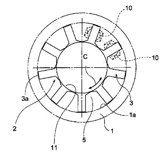
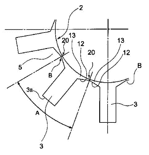
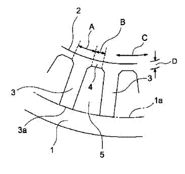
[0023] Next, suitable application forms of the motor stator structure invention will be described with reference to the drawings. In addition, the same or equivalent parts as conventional examples will be described using the same symbols. exist figure 1 and image 3 Among them, the part indicated by symbol 1 is the fixed part iron core composed of a wheel-shaped laminated structure, and the wheel-shaped stator gear body 2 having a plurality of stator teeth parts 3 is mounted on the fixed part iron core 1 by using a press-fitting process or the like. inside.

[0024] The outer peripheral surface 3a of each stator tooth part 3 of the above-mentioned wheel-shaped stator gear body 2 is connected to the inner peripheral surface 1a of the fixed part iron core 1, and a stator coil 10 is installed on the stator tooth part 3, and the stator coil 10 is located on each stator tooth. In the tooth groove 5 between parts 3 and 3.

[0025] On the inner peripheral position 11 of the botto...


PUM


Abstract

The invention aims at preventing a wheel-shaped stator tooth structure from being deformed by eliminating connecting portions between stator tooth portions to form a thinner middle portion and absorbing force caused by interference among iron cores at a fixed portion. A motor stator structure is provided with a pair of conical tooth portions facing to two sides of an inner circumferential position of each stator tooth portion, and the thinner middle portion is formed between the conical tooth portions which are adjacent to each other instead of the connecting portion and used for bearing the force caused by the interference among the iron cores at the fixed portion.

Description

technical field [0001] The present invention relates to the stator structure of the motor, which is mainly to reduce the length of the connection part (generally called bridge) in the circumferential direction between the stator teeth of the wheel-shaped stator gear body installed inside the iron core of the wheel-shaped fixed part to zero. , and use the thinner middle part formed by the adjacent conical teeth for connection, in this way bear the disturbing force generated when the wheel-shaped stator gear body is installed in the iron core of the fixed part, and realize the fixation in this new improved way The installation of the wheel-shaped stator gear body in the external iron core is simplified. Background technique [0002] The same type of motor stator structure used in the past is usually as follows image 3 in the structure. image 3 Only a part is shown in the figure, and the wheel-shaped stator gear body 2 is installed on the inner side of the wheel-shaped fixed ...

Claims


Application Information

Patent Timeline
Patent Type & Authority Applications(China)
IPC IPC(8): H02K1/12H02K1/14
Inventor 城下健治细泽和司
Owner 多摩川精密电机(苏州)有限公司
Why Eureka
Try Eureka