Supercharge Your Innovation With Domain-Expert AI Agents!

Special live-axle hub motor for electric vehicle

A technology of electric vehicles and axle wheels, applied in the field of electric vehicles, can solve problems such as inconvenient mass production and daily maintenance, reduced reliability of electrical connections, loss of installation bases, etc.

Inactive Publication Date: 2012-06-20
河南超微电动汽车有限公司
View PDF0 Cites 2 Cited by
  • Summary
  • Abstract
  • Description
  • Claims
  • Application Information

AI Technical Summary

Problems solved by technology

However, the current in-wheel motors are all dead-axis motors in which the wheel shaft cannot be pulled out from the motor, because the stator of the motor is directly fixed on the wheel shaft, and the wheel hub rotor located on the periphery of the stator and also serving as the motor casing also passes through the bearings on both sides of the stator Rotate the motor fixed on the wheel shaft, making the wheel shaft an indispensable mounting base for the hub motor
The hub motor with this structure cannot be disassembled from the wheel shaft as a whole, because once removed, the stator and rotor of the hub motor will lose the installation base and be dislocated and scattered, and they will not be integrated.
The hub motor with such a structure in the electric vehicle makes it very inconvenient to load and disassemble the driving wheel, which is not convenient for mass production and daily maintenance; in addition, all the wires of this hub motor pass through the threading hole in the wheel shaft and go out of the motor body, and are exposed. Connecting with the controller line connector outside not only adds a manual connection process, but also easily short-circuits in water and reduces the reliability of the electrical connection

Method used


Image

  • Special live-axle hub motor for electric vehicle
  • Special live-axle hub motor for electric vehicle
  • Special live-axle hub motor for electric vehicle

Examples


Embodiment Construction

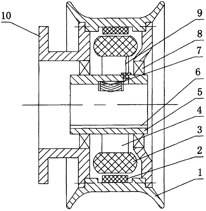
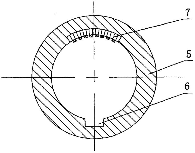
[0014] figure 1 , figure 2 The shown live shaft hub motor includes a hollow casing 5, and a stator is fixed on the outer wall of the hollow casing. The stator includes a coil 3 and a stator bracket 4 installed on the hollow casing. On the outer walls of the hollow casing on both sides of the stator Bearing 8 is also housed respectively, and the hub rotor 1 that is positioned at stator periphery and double as motor housing is installed on the bearing 8, and there is magnetic steel 2 on the inwall of hub rotor. The inner wall of the hollow sleeve is provided with an axially penetrating keyway 6, and the middle section of the inner wall of the hollow sleeve is provided with a sinking groove at the position opposite to the keyway. The wire hole on the casing wall, the sinker is embedded with an elastic electrical connection terminal 7, the motor coil lead wire 9 passes through the wire hole and is electrically connected to the elastic electrical connection terminal 7, and the el...


PUM


Abstract

The invention relates to a special live-axle hub motor for an electric vehicle, which comprises a stator, a rotor and a hollow sleeve. The stator is fixedly mounted on the outer wall of the middle section of the hollow sleeve, two bearings are mounted at two ends of the hollow sleeve and close to two sides of the stator respectively, hub rotors are mounted on the bearings at two ends of the hollow sleeve, a key slot running through axially and a first elastic electric connecting terminal connected with a stator coil of the motor electrically are arranged on the inner wall of the hollow sleeve, a key matched with the key slot and a second elastic electric connecting terminal are arranged on an axle correspondingly, the first elastic electric connecting terminal and the second elastic connecting terminal are connected electrically automatically after the hub motor is inserted onto the axle, and circuits of the stator coil and an automatic controller are switched on, so that the hub motor can work normally under control of the controller. A special waterproof device is added, so that connection of driving circuits can be simple and reliable, and a driving motor on the electric vehicle can be produced, assembled, maintained, mounted and demounted conveniently.

Description

technical field [0001] The invention relates to the technical field of electric vehicles, in particular to a live shaft hub motor dedicated to electric vehicles. Background technique [0002] Wheel hub motors have been widely used in electric bicycles, and their application in the field of electric vehicles has also begun. However, the current in-wheel motors are all dead-axis motors in which the wheel shaft cannot be pulled out from the motor, because the stator of the motor is directly fixed on the wheel shaft, and the wheel hub rotor located on the periphery of the stator and also serving as the motor casing also passes through the bearings on both sides of the stator Rotating the motor fixed on the wheel shaft makes the wheel shaft an indispensable installation base for the hub motor. The hub motor with this structure cannot be disassembled from the wheel shaft as a whole, because once it is removed, the stator and rotor of the hub motor will lose the installation base ...

Claims


Application Information

Patent Timeline
IPC IPC(8): H02K7/10B60K7/00
Inventor 董建国
Owner 河南超微电动汽车有限公司
Features
  • R&D
  • Intellectual Property
  • Life Sciences
  • Materials
  • Tech Scout
  • Unparalleled Data Quality
  • Higher Quality Content
  • 60% Fewer Hallucinations
Learn More