Protective Cap Assembly with Leak Detection Capability for Pressure Valves
What is Al technical title?
Al technical title is built by PatSnap Al team. It summarizes the technical point description of the patent document.
A technology of pressure valve and cap assembly, which is used in valve devices, engine components, mechanical equipment, etc.
Active Publication Date: 2014-10-08
TAYLOR INNOVATIONS
View PDF4 Cites 0 Cited by
Summary
Abstract
Description
Claims
Application Information
AI Technical Summary
This helps you quickly interpret patents by identifying the three key elements:
Problems solved by technology
Method used
Benefits of technology
Problems solved by technology
[0003] When used, weather covers as taught in Kenny's '282 patent are generally only used to provide visual notification when the pressure relief valve is open, and do not Detect other harmful conditions, such as leaks in shut-off valves, etc.
Method used
Image
Click on the blue label to locate the original text in one second.
Reading with bidirectional positioning of images and text.
Examples
Embodiment Construction
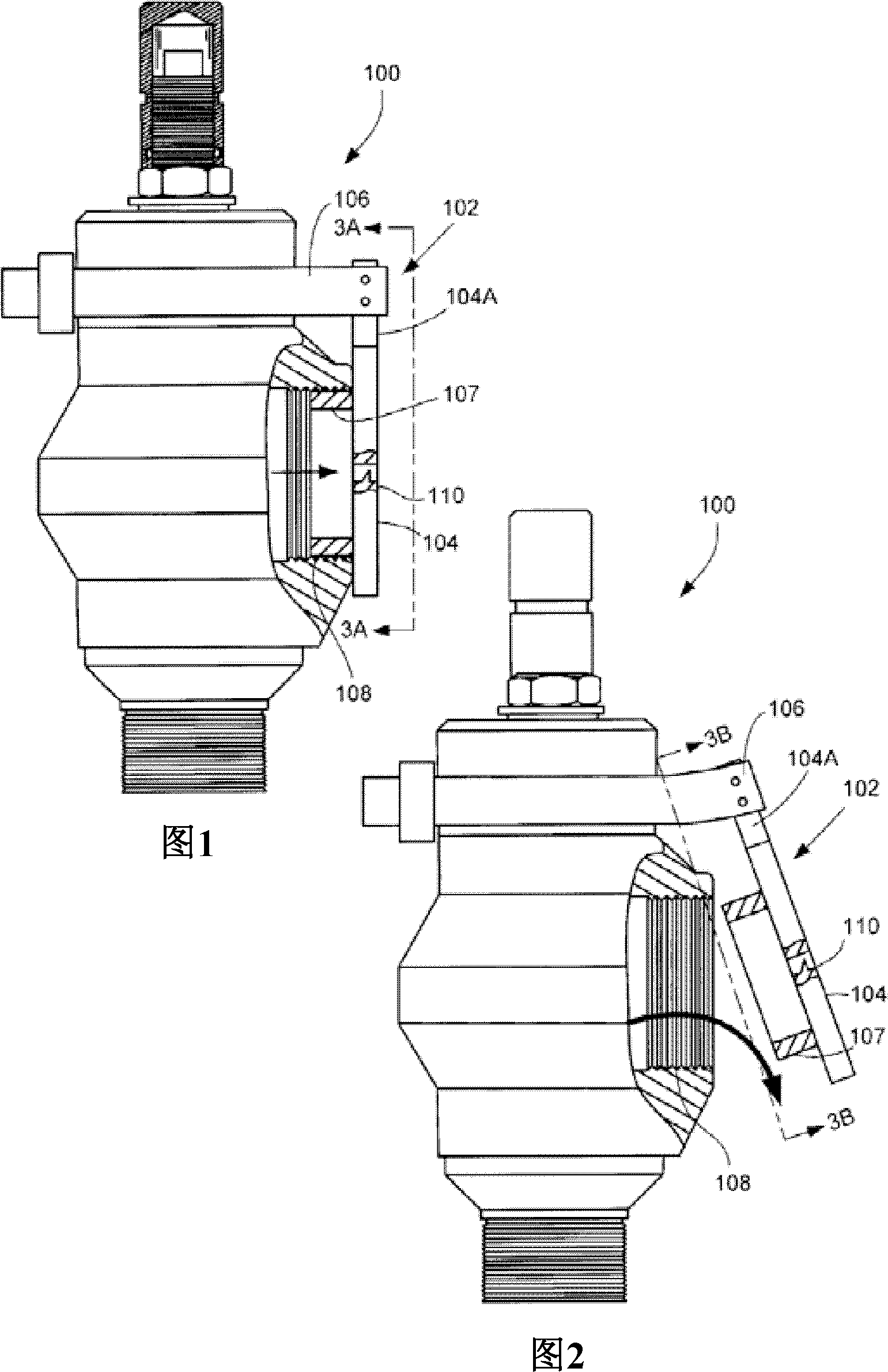
[0041] Without limitation, embodiments of the present invention generally relate to an environmental protection cap assembly for providing human sensory cues to indicate fluid flow in a pressurized fluid system.
[0042] As described below, in some embodiments, the cap assembly is configured to cover a discharge conduit downstream of a pressure valve for discharging fluid to ambient air. The cap assembly provides a cue by providing an audible and / or visual cue that fluid flow through the valve has a low level of leakage. In some embodiments, a whistle may be used to provide an audible cue to indicate a leak; in other embodiments, an LED may be used to provide a visual cue to indicate a leak.
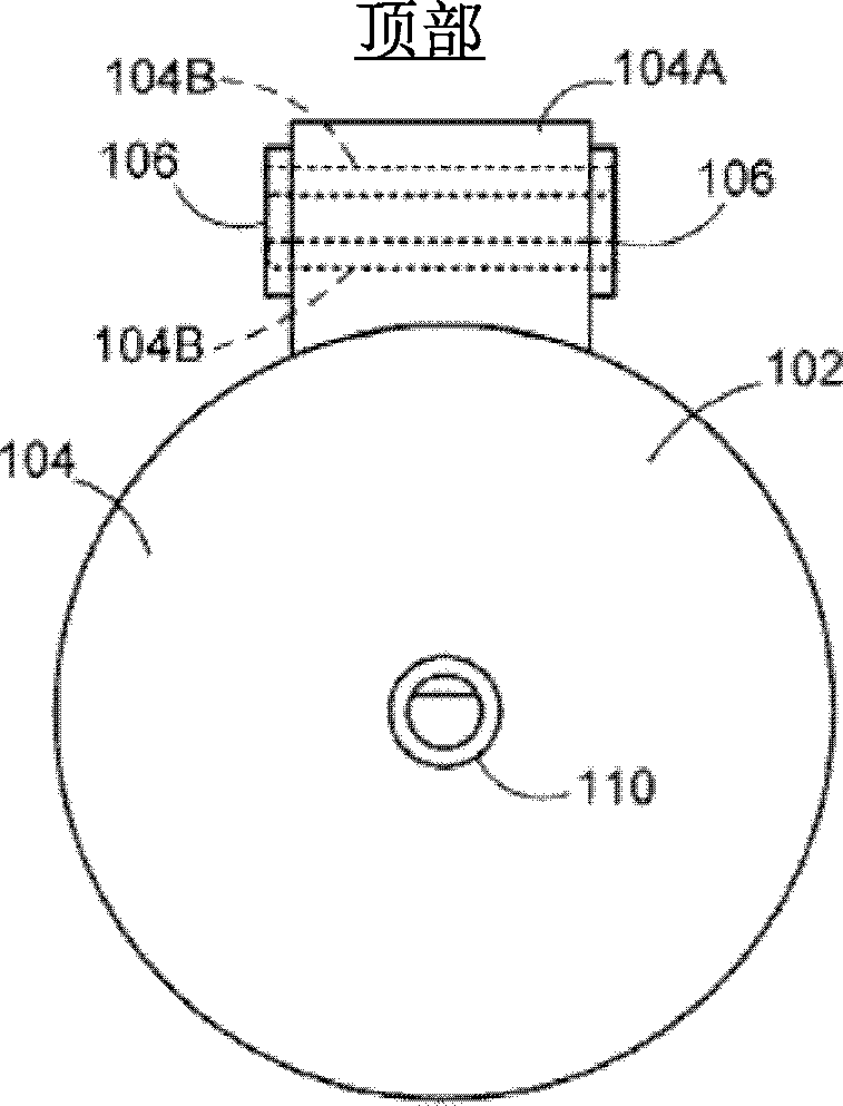
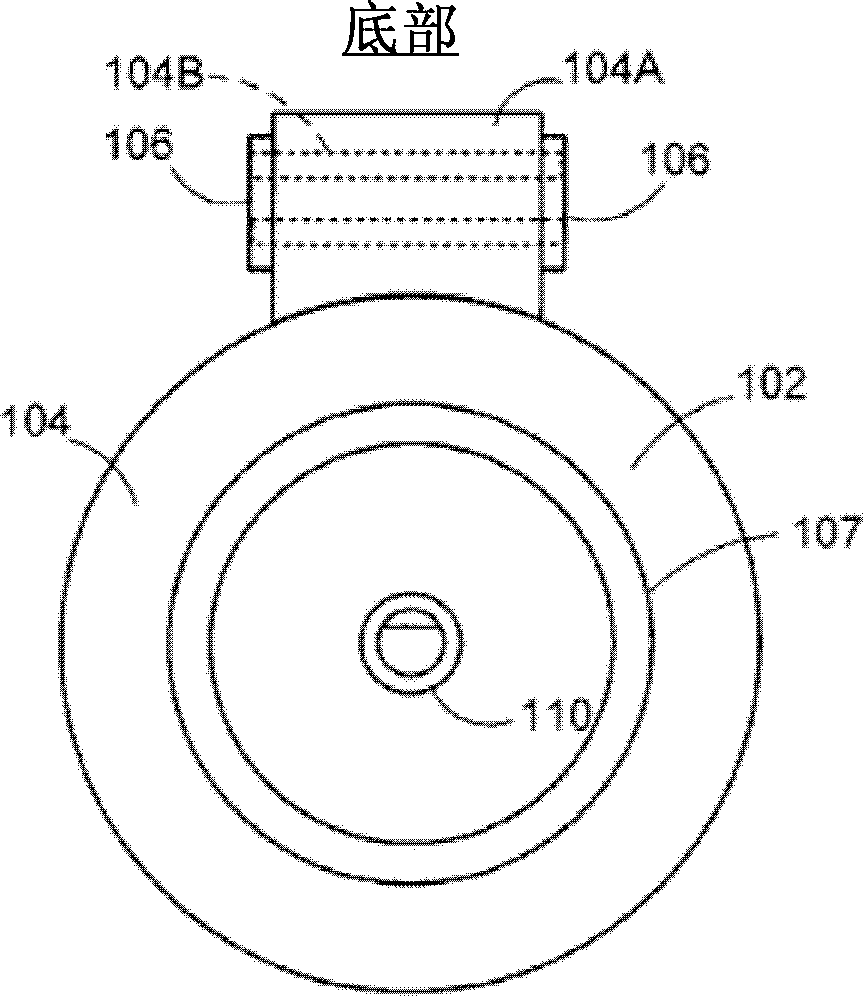
[0043] figure 1 Pressure relief valve 100 is shown provided with an environmental protection cap assembly 102 associated therewith. The pressure relief valve 100 is of the normally closed type so that during normal processing, upstream pressurized fluid (such as gas or liquid) is pass...
PUM
Abstract
A cap assembly (102, 120, 130, 140, 150, 170, 190, 200, 230, 250, 280) for detecting leaks through a pressure valve (100, 202). According to various embodiments, the cap assembly comprises a body (104, 121, 141, 141, 152, 171, 191, 204, 232, 252) arranged in fluid communication with the valve; and a sensor (110, 110A, 110B, 174, 192, 214, 238, 262, 282), supported by the body to provide a human sensory cue indicating leakage of pressurized fluid from the valve in the closed position. In various embodiments, the sensory prompter may be a whistle that emits an audible sound, a light emitting device that emits visible light, and the like. In a further embodiment, the cap assembly body may be connected to the conduit (122) via a tether (106, 124, 154, 206, 254) and release pressure from the conduit in response to venting pressurized fluid when the valve transitions to the open position. pop up.
Description
Background technique [0001] Pressurized fluids, such as liquid or gaseous hydrocarbons, steam and water, can be transported and channeled through a network of pipes. Various pressure valve structures are used to guide and regulate the flow of fluid flowing through the pipeline network, such as: pressure relief valve, emergency shut-off valve, vent valve, flapper valve, ball valve, pressure reducing valve, etc., also known as anti-shock door (Chokes ). [0002] Some valves, such as some normally closed pressure relief valve type valves, are capable of venting a portion of the fluid to an alternative path, eg, to ambient air, when a high or low pressure threshold is reached. It is known to provide removable weather covers on vertically extending discharge pipes in order to prevent the ingress of foreign matter, for example into the discharge pipe. It is also known to tether the cap so that when the pressure relief valve is jacked open, the cap is blown away from the discharge ...
Claims
Application Information
Patent Timeline
Application Date:The date an application was filed.
Publication Date:The date a patent or application was officially published.
First Publication Date:The earliest publication date of a patent with the same application number.
Issue Date:Publication date of the patent grant document.
PCT Entry Date:The Entry date of PCT National Phase.
Estimated Expiry Date:The statutory expiry date of a patent right according to the Patent Law, and it is the longest term of protection that the patent right can achieve without the termination of the patent right due to other reasons(Term extension factor has been taken into account ).
Invalid Date:Actual expiry date is based on effective date or publication date of legal transaction data of invalid patent.