Heat pipes and thermoelectric cooling devices

A technology for thermoelectric cooling and thermoelectric devices, used in refrigerators, indirect heat exchangers, refrigeration and liquefaction, etc.

Active Publication Date: 2012-06-20
SHEETAK INC
View PDF10 Cites 26 Cited by
  • Summary
  • Abstract
  • Description
  • Claims
  • Application Information

AI Technical Summary

Problems solved by technology

[0006] Although vapor diode based heat pipes have been developed before, there is room for improvement in terms of their structure as well as their attachment to thermoelectric devices

Method used


Image

  • Heat pipes and thermoelectric cooling devices
  • Heat pipes and thermoelectric cooling devices
  • Heat pipes and thermoelectric cooling devices

Examples


Embodiment Construction

[0030] Before describing in detail the embodiments according to the present invention, it should be noted that these embodiments pertain primarily to thermoelectric cooling systems with heat pipes. Accordingly, system components have been described to show only those specific details suitable for understanding the embodiments of the invention and not to show details that are obvious to those skilled in the art.

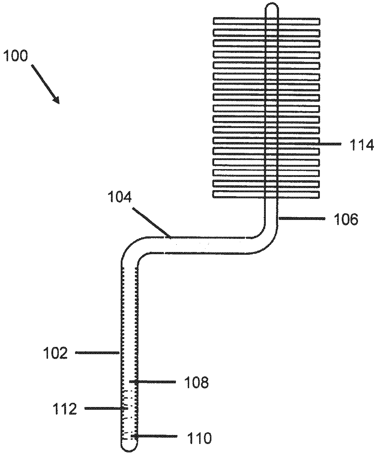
[0031] figure 1 A cross-sectional view of a heat pipe 100 according to an embodiment of the present invention is shown.

[0032] The heat pipe 100 includes three sections—an evaporating section 102 , an adiabatic section 104 , and a condensing section 106 . The evaporation section 102 includes a chamber 108 and a fluid reservoir 110 containing a working fluid 112 . In an embodiment of the present invention, the evaporation portion 102 is a sintered surface, a grooved surface, or a mesh surface to enhance evaporation.

[0033] The working fluid 112 is selected based...


PUM


Abstract

In various embodiments of the present invention, a thermoelectric cooling device with a thermoelectric device, heat pipe and a heat sink is provided. The thermoelectric device is connected to a chamber through a metal standoff. The chamber contains a fluid that needs to be cooled. The metal standoff has a shape, e.g. a bevel shape, to minimize heat leakage into the fluid. The heat pipes are preferably connected to the thermoelectric device with a Thermal Interface Material (TIM). In one embodiment, the heat pipes are attached to the thermoelectric device through screws which have an insulating standoff so as to minimize heat leakage into the fluid. In another embodiment of the present invention, two stage thermoelectric cooling devices with multiple heat pipes and common heat sink are provided to cool the fluid.

Description

technical field [0001] The present invention relates to thermoelectric cooling systems. More specifically, the present invention relates to thermoelectric cooling systems with heat pipes and heat sinks. Background technique [0002] As an alternative to conventional vapor compression systems, thermoelectric cooling systems are reliable, lightweight and environmentally friendly. Conventional thermoelectric cooling systems use one or more thermoelectric devices and a DC power source for cooling purposes. In cooling the chamber, the thermoelectric device transfers heat from the cold side of the thermoelectric device to the hot side of the thermoelectric device. [0003] When the thermoelectric cooling system is turned off, heat flows through the thermoelectric device from the hot side to the cold side, thereby warming the chamber to ambient temperature. [0004] Thus, conventional thermoelectric cooling systems need to be turned on for extended periods of time to keep the ch...

Claims


Application Information

Patent Timeline
Patent Type & Authority Applications(China)
IPC IPC(8): F28D15/00
CPCF25B2321/025F28D15/0266F28D15/0275H01L35/30F28D15/04F25B21/02H10N10/13
Inventor 乌塔姆·戈沙尔阿扬·古哈
Owner SHEETAK INC
Why Eureka
Try Eureka