Multifunctional electric cup

An electric heating cup and multi-functional technology, which is applied to washing devices, hand irons, appliances for boiling water, etc., can solve the problems of low safety factor, different power of electric heating cups, unreliable heating circuit settings, etc., and achieves the effect of high practicability.

Active Publication Date: 2012-06-27
NINGBO SHUAIWEI ELECTRIC APPLIANCE
View PDF4 Cites 1 Cited by
  • Summary
  • Abstract
  • Description
  • Claims
  • Application Information

AI Technical Summary

Problems solved by technology

[0006] There are many electric heating cups on the market. In addition to heating general liquids, they can also generate steam. However, the heating circuit is often unreliable. When heating liquids, there will be dry burning. When generating steam, the efficiency is not high and the safety factor is not continuous. Low, it may cause harm not only to the appliance itself but also to the user
When a cup cover with other functions is installed on the cup body of the electric heating cup, especially when steam is generated, if the seal between the cup cover and the cup body is not good, the steam will leak and easily burn the user
In addition, when carrying an electric heating cup during travel, the power of the electric heating cup may be different due to the different voltage of the power supply used, and the function of the electric heating cup cannot be well realized, especially when the electric heating cup suitable for low voltage only has high voltage, it will not be able to May burn if used or forced

Method used


Image

  • Multifunctional electric cup
  • Multifunctional electric cup
  • Multifunctional electric cup

Examples


Embodiment Construction

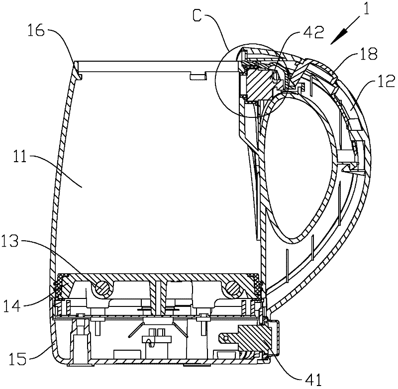
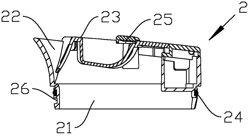
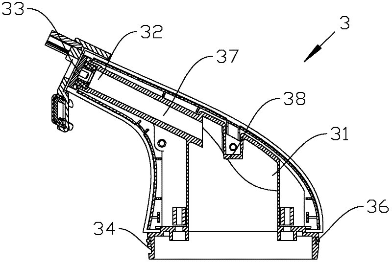
[0030] Such as Figures 1 to 7 Shown is a structural schematic diagram of an embodiment of the present invention, a multifunctional electric heating cup, including a cup body 1 with a handle 12, a cup body 11 for containing liquid and a heating assembly for heating the liquid are arranged in the cup body, so The heating assembly includes at least two electric heating tubes 13 and a control circuit for controlling the working state of the electric heating tubes. The control circuit has a voltage switch 43. The electric heating tubes include electric heating tubes I131 and electric heating tubes II132 connected in parallel in the control circuit. In the voltage state, the electric heating tube I and the electric heating tube II are both in the working state through the voltage switching switch. The power remains the same when switching between liquid and steam generating functions and between high and low voltage. The control circuit also has a bidirectional power switch 41 wit...


PUM


Abstract

The invention discloses a multifunctional electric cup, which comprises a cup body with a handle. A cup unit for containing liquid and a heating assembly for heating the liquid are disposed in the cup body, the heating assembly comprises at least two tubular electric heating elements and a control circuit for controlling the work states of the tubular electric heating elements, the control circuit is provided with a voltage selector switch, the tubular electric heating elements comprise a tubular electric heating element I and a tubular electric heating element II which are parallelly connected into the control circuit, when in a low voltage state, both the tubular electric heating element I and the tubular electric heating element II are in work states by the aid of the voltage selector switch, and when in a high voltage state, the tubular electric heating element I or the tubular electric heating element II is independently in a work state by the aid of the voltage selector switch. A double voltage design is adopted, functions of heating the liquid and generating steam of the electric cup are switched by a bidirectional power switch, the work states of the tubular electric heating element I and the tubular electric heating element II are changed by the aid of the voltage selector switch, so that the multifunctional electric cup can work between different work voltages but the powers keep consistent, and the multifunctional electric up is convenient, fast, safe and reliable, and is high in practicality.

Description

[0001] The patent application for this invention is a divisional application [0002] The filing date of the original application is: August 18, 2010 [0003] The application number is: 201010258903.1 [0004] The name of the invention is: a multifunctional electric heating cup. technical field [0005] The invention relates to domestic electric appliances, in particular to a multifunctional electric heating cup. Background technique [0006] There are many electric heating cups on the market. In addition to heating general liquids, they can also generate steam. However, the heating circuit is often unreliable. When heating liquids, there will be dry burning. When generating steam, the efficiency is not high and the safety factor is not continuous. Low, it may cause harm not only to the appliance itself but also to the user. When a cup cover with other functions is added to the cup body of the electric heating cup, especially when steam is generated, if the seal between t...

Claims


Application Information

Patent Timeline
Patent Type & Authority Applications(China)
IPC IPC(8): A47J27/21D06F75/20D06F75/14D06F75/24
Inventor 张建炜
Owner NINGBO SHUAIWEI ELECTRIC APPLIANCE
Why Eureka
Try Eureka