Stab target for dynamic response fencing training
A target and response technology, applied in the field of fitness equipment and sports training, can solve the problem of insufficient training of athletes, and achieve the effect of training reaction speed and hitting accuracy
- Summary
- Abstract
- Description
- Claims
- Application Information
AI Technical Summary
Problems solved by technology
Method used
Image

Examples
specific Embodiment approach 1
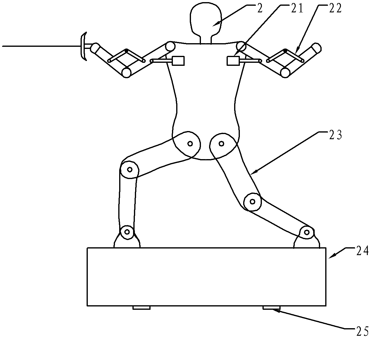
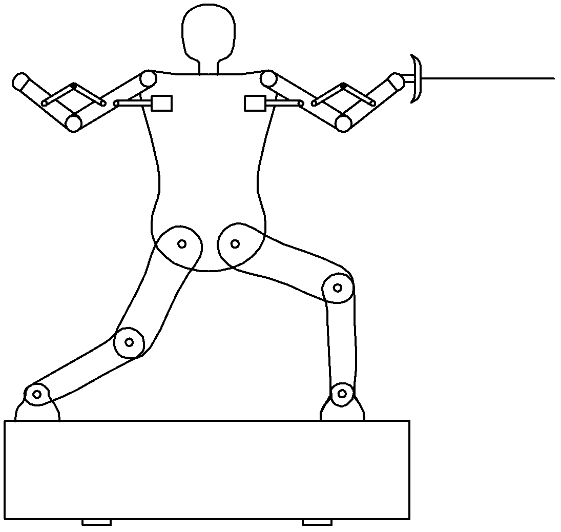
[0018] Embodiment 1: The stabbing target for dynamic response fencing training described in this embodiment includes a target stabbing body 2, a stabbing indicating device 1 and a control device 3, and the target stabbing body 2 is a human figure with limbs, The stabbing indicating device 1 is composed of a plurality of indicating units. According to the rules of fencing, each effective part of stabbing on the target stabbing body 2 is covered and fixed with an indicating unit. Each indicating unit is provided with a luminous body to control The device 3 is composed of a controller 31 and a plurality of sensors 15, each sensor 15 cooperates with an indicating unit for collecting the stabbing signal received by the indicating unit, and the signal output ends of the plurality of sensors 15 are respectively connected to the controller 31 The multiple stabbing signal input terminals of the controller 31 are respectively connected to the control signal input terminals of the multipl...
specific Embodiment approach 2
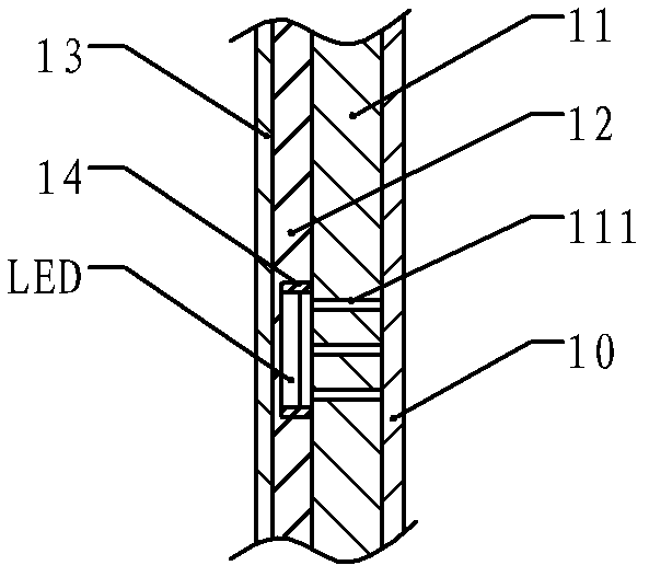
[0026] Specific implementation mode two: see image 3 To describe this embodiment, image 3 The present embodiment is a further description of the structure of the indicating unit of the stabbing indicating device 1 in the first specific embodiment: in the present embodiment, the indicating unit is a sheet with a thickness, and the indicating unit consists of a bottom layer 13 , light-transmitting layer 10, luminous body fixing layer 12, buffer layer 11 and luminous body LED, the bottom layer 13 and the edges of the light-transmitting layer 10 are fixedly connected to form a sealed cavity, and the luminous body fixing layer 12, buffer layer 11 and The luminous body LEDs are all fixed in the wall, the luminous body fixed layer 12 is fixed on the bottom layer 13, the buffer layer 11 is located between the luminous body fixed layer 12 and the light-transmitting layer 10, and the luminous body fixed layer 12 is set There are one or more grooves or through holes, the illuminant LE...
specific Embodiment approach 3
[0028] Specific implementation mode three: see image 3 Describe this embodiment, this embodiment is to further limit the structure of the indicating unit of the stabbing indicating device 1 in the second specific embodiment, the indicating unit in this embodiment also includes a luminous body protective cover 14, the luminous body The protective cover 14 is set on the outside of the luminous body, and the height of the protective cover 14 is greater than that of the LED of the luminous body, and smaller than the thickness of the fixing layer 12 of the luminous body.
[0029] The protective cover 14 added in this embodiment can effectively prevent the luminous body from being damaged due to excessive stabbing force.
PUM
 Abstract
Description
Claims
Application Information