Apparatus for monitoring a fluid

a technology of fluid monitoring and apparatus, which is applied in the direction of instruments, testing water, food, etc., can solve the problem of delay before an accurate temperature measurement can be read, and achieve the effect of increasing ion concentration, improving ion concentration, and reducing the number of instruments

Active Publication Date: 2021-12-23
4T2 SENSORS LTD
View PDF6 Cites 0 Cited by
  • Summary
  • Abstract
  • Description
  • Claims
  • Application Information

AI Technical Summary

Benefits of technology

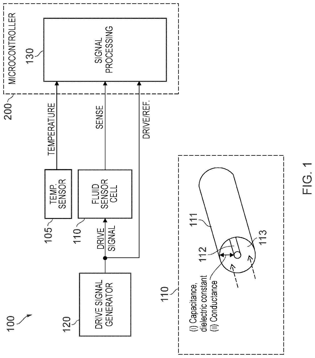
[0211]It is to be understood that, for aqueous solutions containing ionic substances such as sodium hydroxide, sodium chloride or any other ionic substance of interest, at relatively low concentrations of dissolved ions the dielectric constant εr of the solution may be substantially the same as that of water with a substantially zero concentration of the ions therein. Since the dielectric constant εr of water is known to be a function of temperature, measurements of the dielectric constant εr of the liquid containing the (relatively low) concentration of dissolved ions is capable of providing a precise and accurate measurement of the temperature of the liquid.
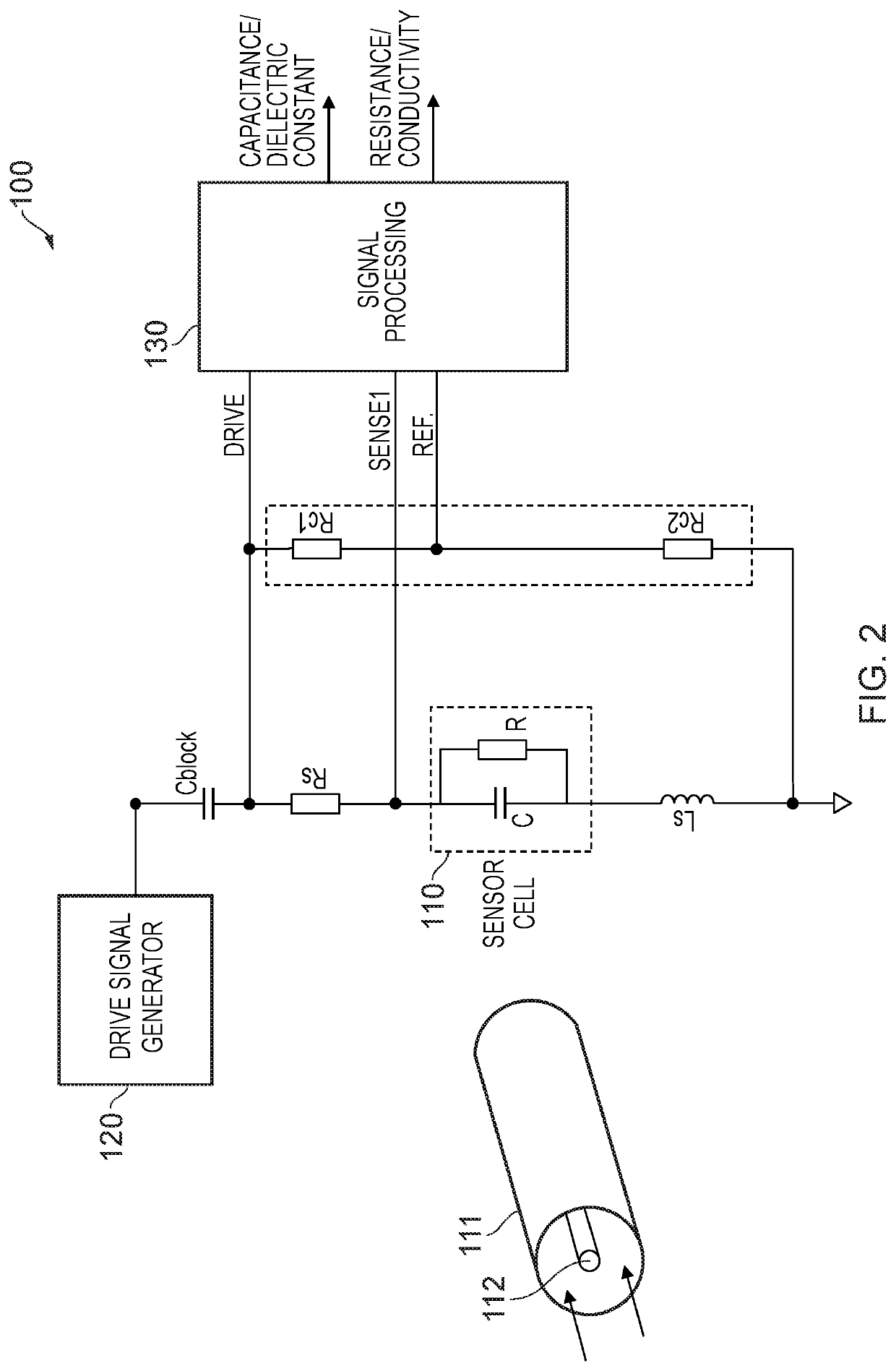
[0212]Embodiments of the present invention permit measurements of dielectric constant based on measurements of capacitance of a capacitive fluid sensor and conductivity of the medium therebetween. It is to be understood that measurements of capacitance of the fluid sensor may be affected by electrode polarisation, which effect increases with increasing ion concentration. Consequently, the value of dielectric constant of the fluid calculated using measured values of capacitance provide erroneous results. Embodiments of the present invention permit the effects of electrode polarisation due to the dissolved ions to be compensated for. In one aspect, compensation is achieved by measuring the capacitance and conductivity of a liquid and determining what the capacitance of the liquid would be if the conductivity of the liquid was substantially zero. This may be done if the gradient of a plot of capacitance as a function of conductivity for the aqueous solution of interest is known, by extrapolation. The corresponding value of capacitance at substantially zero conductivity (i.e. a value of capacitance compensated for the effects of electrode polarisation) may then be used to calculate the dielectric constant εr of the solution. This value of dielectric constant εr can then be employed to obtain a value of temperature assuming that the dielectric constant εr of the liquid so calculated is substantially equal to the of water at the same temperature.
[0213]Thus, given information in respect of the relationship between the dielectric constant εr of water and temperature (such as an algorithm equating the two, a look up table or other form) it is possible to calculate the temperature of the liquid from the information. It is to be understood that electrical measurements of capacitance and conductivity may be made relatively quickly, permitting relatively rapid determination of the temperature of a liquid to very high precision. It is to be understood that embodiments of the present invention have the very significant advantage that the measurements are made directly on the liquid itself, and do not rely on thermal equilibration of the liquid with the sensor (such as a thermocouple) or a body in thermal contact with the liquid, the temperature of which is measured such as the housing of the sensor in the case that infra-red (IR) measurement techniques are employed.

Problems solved by technology

A conventional thermometer has to reach thermal equilibrium with the body being measured, which introduces a delay before an accurate temperature measurement can be read.

Method used


Image

  • Apparatus for monitoring a fluid
  • Apparatus for monitoring a fluid
  • Apparatus for monitoring a fluid

Examples


example fluids

[0375

[0376]An example application of the apparatus is to control the mixture and composition of emulsion cutting fluids. The proportion of oil to water is to be controlled. The ratio of oil to water can be determined by measuring the dielectric constant of the fluid. Water has a dielectric constant of around 80 at 20 degrees Celsius, and the oil component has a dielectric constant <10. Evaporation of water from the fluid causes the oil to water ratio to increase, and so it is necessary to add water to keep the emulsion concentration within the required limits.

[0377]Dielectric constant of the fluid is approximately equal to the average by volume of the two components, so for a 10% mix we would expect to see a dielectric constant of around 72. The surfactant used to keep the oil droplets in suspension is conductive as it has ionic components. Conductivity alone cannot be used to determine the emulsion concentration, as conductivity is affected by other factors such as water hardness a...


PUM

PropertyMeasurementUnit
conductivityaaaaaaaaaa
frequencyaaaaaaaaaa
frequencyaaaaaaaaaa

Abstract

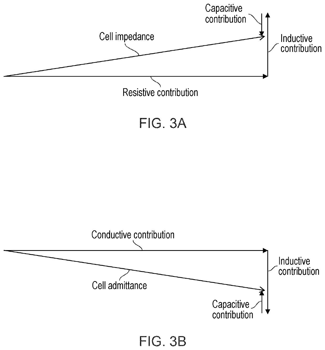
A processing apparatus (700) is configured to receive a sense signal from a capacitive fluid sensor (610) comprising a first electrode (611) and a second electrode (612) with a sensing region (613) between the electrodes. The processing apparatus (700) is configured to receive an alternating drive signal applied to the capacitive fluid sensor (610). The processing apparatus (700) is configured to determine a complex impedance of the fluid sensor (610) based on the sense signal and the drive signal, the complex impedance comprising an in-phase component indicative of a conductivity quantity of a fluid in the sensing region and a quadrature component indicative of a capacitance quantity of the fluid sensor. The processing apparatus (700) is configured to determine a temperature of the fluid in dependence on at least the determined capacitance quantity of the fluid sensor (610).

Description

TECHNICAL FIELD[0001]The present invention relates to apparatus and a method for monitoring a fluid.BACKGROUND[0002]There are various applications where it is desirable to monitor a property of a fluid. One application is cleaning of debris and residue from internal surfaces in industrial processing plants which process liquids, such as plants processing chemicals, foodstuffs, beverages and other fluids. Such cleaning processes may be referred to as ‘clean in place’ (CIP) processes.[0003]Sodium hydroxide solution is often employed in CIP processes. An aqueous solution of sodium hydroxide is pumped through pipework of the plant to clean the internal surfaces.[0004]There is a need to determine when it is safe to reuse the processing plant after cleaning. It is important to thoroughly cleanse the internal surfaces of sodium hydroxide (or other cleaning substance) following treatment so as to avoid contamination of liquids subsequently passed through the plant with sodium hydroxide. Rem...

Claims


Application Information

Patent Timeline
Patent Type & Authority Applications(United States)
IPC IPC(8): G01N27/04G01N27/06G01N27/22G01N33/14
CPCG01N27/046G01N33/14G01N27/228G01N27/06G01N33/18G01N27/028
Inventor SMITH, ALEXANDER EDWARDSWINBOURNE, MAXIM HARRY JOSEPH
Owner 4T2 SENSORS LTD
Why Eureka
Try Eureka