Conical air floating shaft system

A technology for air-floating shafts and air-floating spindles, applied to bearings, shafts and bearings, mechanical equipment, etc., can solve the problems of easy dry friction and low positioning accuracy of air-floating shafting, achieve high centering accuracy and improve rigidity , Guarantee the effect of rotation accuracy

Inactive Publication Date: 2012-06-27
西安威而信精密仪器有限公司
View PDF5 Cites 14 Cited by
  • Summary
  • Abstract
  • Description
  • Claims
  • Application Information

AI Technical Summary

Problems solved by technology

[0004] In order to solve the technical problems of low positioning accuracy and easy dry friction in the existing air-floating shafting system, the present invention provides a conical air-floating shafting system, which not only integrates the advantages of the air-floating shafting shaft, Moreover, the tapered fit between the air-floated spindle and the air-floated bushing can effectively improve the rigidity of the shafting system. At the same time, due to the high centering accuracy of the tapered surface fit, it can ensure that the air-floated shafting system still has a high end surface off the shaft. higher precision

Method used


Image

  • Conical air floating shaft system
  • Conical air floating shaft system

Examples


Embodiment Construction

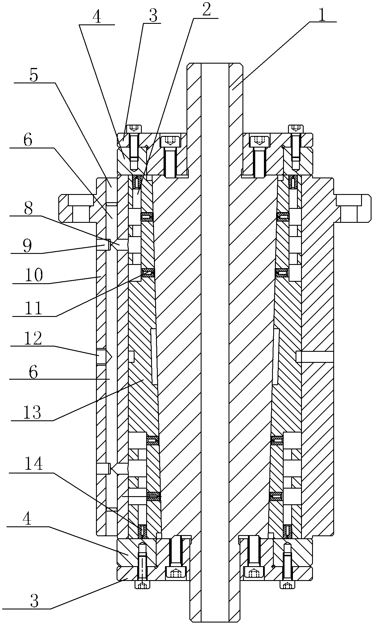
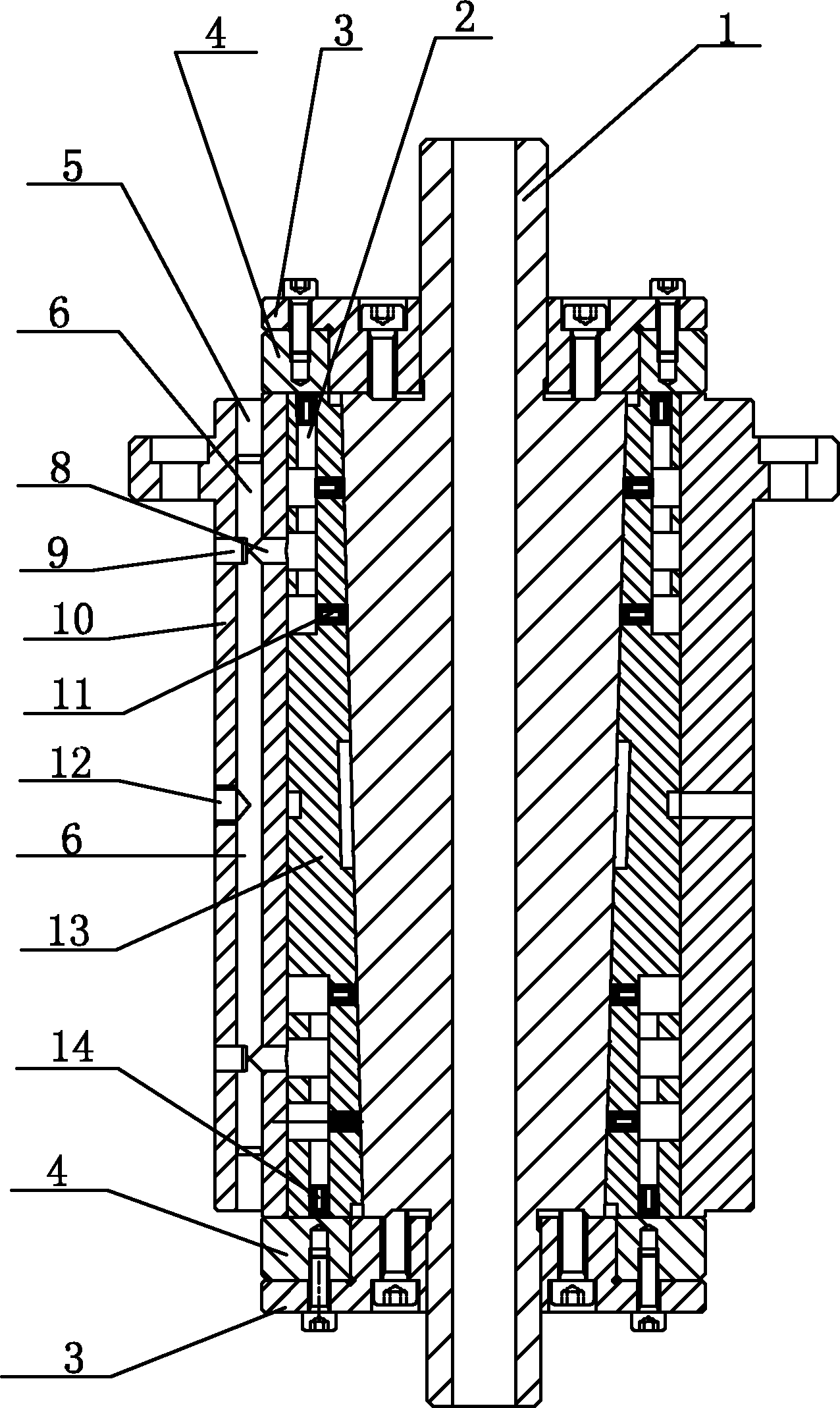
[0018] Such as figure 1 As shown, the conical air bearing shaft system includes the air bearing main shaft 1, the air bearing inner shaft sleeve 13 cooperating with the air bearing main shaft and arranged outside the air bearing main shaft, and the air bearing inner shaft sleeve cooperating with the air bearing inner shaft sleeve 13 The outer air-floating outer shaft sleeve 10 and the positioning plate 3 arranged at both ends of the air-floating main shaft 1, the positioning plate 3 is fixedly connected with the air-floating main shaft 1, and the two ends of the air-floating outer shaft sleeve 13 are provided with a thrust plate 4, the thrust plate 4 Plate 4 and positioning plate 3 are fixedly connected,

[0019] There is an air cavity 6 on the air flotation outer shaft sleeve. The air cavity 6 divides the air flotation outer shaft sleeve into an outer wall and an inner wall. The nozzle 12 is provided with an air outlet 8 communicating with the air chamber 6 on the inner wall...


PUM


Abstract

The invention relates to a conical air floating shaft system, which comprises an air floating main shaft, an air floating inner shaft sleeve, an air floating outer shaft sleeve, and positioning plates, wherein the air floating inner shaft sleeve is arranged on the outer side of the air floating main shaft, and is matched with the air floating main shaft, the air floating outer shaft sleeve is arranged on the outer side of the air floating inner shaft sleeve, and is matched with the air floating inner shaft sleeve, and the positioning plates are arranged on both ends of the air floating main shaft. The positioning plates are fixedly connected with the air floating main shaft. Both ends of the air floating outer shaft sleeve are provided with an anti-thrust plate. The anti-thrust plate is fixedly connected with the positioning plate. In the prior art, the positioning accuracy of the existing air floating shaft system is not high, and the dry friction is easily generated. With the present invention, the technical problems in the prior art are solved, and the conical air floating shaft system is provided, wherein the conical air floating shaft system integrates the advantages of the air floating main shaft, the air floating main shaft is matched with the air floating shaft sleeves so as to effectively improve the stiffness of the shaft system, the conical surface match is adopted so as to provide high centering accuracy, and it can be ensured that the air floating shaft system of the present invention has high accuracy when the off-axis end surface is high.

Description

technical field [0001] The invention relates to an air-floating shafting system, in particular to a tapered air-floating shafting system. Background technique [0002] Turnover benchmark is one of the core technologies in precision / ultra-precision measuring instruments, experimental equipment and manufacturing equipment. Due to the advantages of high rotary motion precision, high displacement sensitivity and minimal friction loss, the air-bearing shaft system has been increasingly used as a high-precision rotary reference in the above-mentioned equipment. [0003] At present, the basic structure of the commonly used air bearing shaft system is mainly composed of two parts: the air bearing main shaft and the air bearing sleeve. When the air film gap is formed in the axial and radial directions to form gas support and lubrication, the air bearing main shaft can drive the load in the air bearing. Rotary movement in the shaft sleeve. However, the existing air bearing main shaf...

Claims


Application Information

Patent Timeline
Patent Type & Authority Applications(China)
IPC IPC(8): F16C32/06
Inventor 戴桂秋
Owner 西安威而信精密仪器有限公司
Why Eureka
Try Eureka