Moveable guide plate structure for gate valve

A deflector and movable technology, which is applied in the direction of sliding valves, valve devices, engine components, etc., can solve the problem of valves not being tightly closed, and achieve the effect of reducing size

Active Publication Date: 2013-10-30
SUZHOU GAS EQUIP & VALVES MFG
View PDF5 Cites 0 Cited by
  • Summary
  • Abstract
  • Description
  • Claims
  • Application Information

AI Technical Summary

Problems solved by technology

[0003] The technical problem to be solved by the present invention is to provide a movable deflector structure for gate valves, which can solve the problem of lax valve closure caused by accumulation of impurities at the bottom of the valve without affecting the size of the gate valve

Method used


Image

  • Moveable guide plate structure for gate valve
  • Moveable guide plate structure for gate valve

Examples


Embodiment Construction

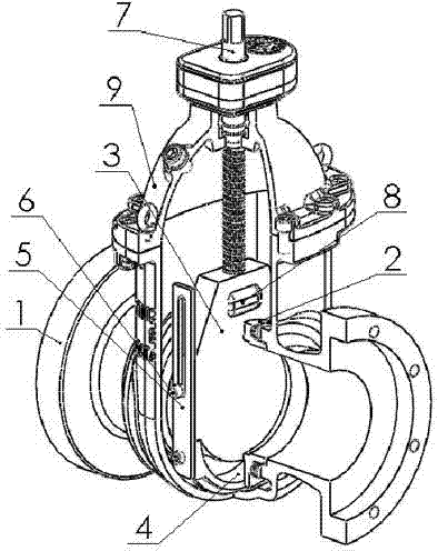
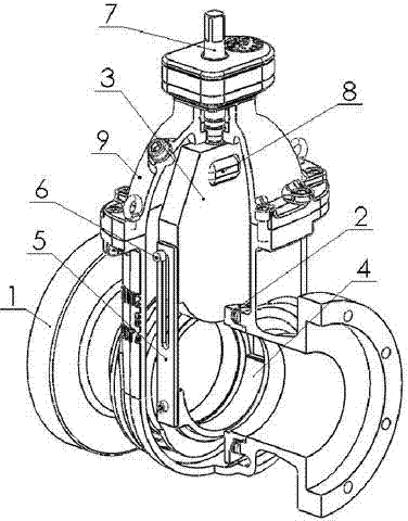
[0011] Such as figure 1 with figure 2 A movable deflector structure of a gate valve is shown, including a valve body 1, a valve cover 9 is provided on the upper part of the valve body 1, a valve seat 2 is provided inside the valve body 1, and a valve seat 2 is provided between the valve seats 2. There is a gate plate 3, the top of the gate plate 3 is fixed with a valve stem nut 8, the valve stem nut 8 is provided with a valve stem 7, and the valve stem 7 is provided with a lifting thread to match the valve stem nut 8, and the valve stem 7 is set on the valve cover 9, the bottom of the gate 3 is provided with a deflector 4 that can move up and down; the two ends of the deflector 4 are respectively fixed with a connecting plate 5, and the connecting plate 5 is provided with a connecting plate groove, and the connecting plate A limit screw 6 is arranged in the groove, and the limit screw 6 is fixed on the gate plate 3 .

[0012] Such as Figure 1 to Figure 2 It shows the gate...


PUM


Abstract

The invention relates to a moveable guide plate structure for a gate valve. The moveable guide plate structure comprises a valve body, wherein a valve cover is arranged on the upper part of the valve body; valve bases are arranged in the valve body; a shutter is arranged between the valve bases; a valve rod nut is fixedly arranged at the top of the shutter; a valve rod is arranged in the valve rod nut; a lifting thread which is arranged on the valve rod is matched with the valve rod nut; the valve rod is arranged on the valve cover; a guide plate capable of moving up and down is arranged at the bottom of the shutter; a connecting plate is respectively fixedly arranged at each of the two ends of the guide plate; a connecting plate slot is formed in the connecting plate; a limiting bolt is arranged in the connecting plate slot; and the limiting bolt is fixedly arranged on the shutter. During the process of opening or closing the valve, the limiting bolts on the two sides of the shutter move in the connecting plate slots at first, and then drive the guide plate to move after the limiting bolts arrive at one ends of the connecting plate slots. During the whole moving process, the guide plate is located between two valve bases, and no clearance exists, so that the problem of impossibility to tightly close the valve caused by the impurities entering into the valve cavity and accumulating at the bottom of the valve is solved, the size of the bottom of the valve is reduced and the economical and energy-saving effects are achieved.

Description

technical field [0001] The invention relates to a gate valve structure in the gate valve industry, in particular to a movable deflector structure of the gate valve. Background technique [0002] At present, when ordinary gate valves manufactured by many domestic companies are in the fully open position and during the opening and closing process, impurities in the pipeline will enter the valve cavity, causing impurities to accumulate at the bottom of the valve, resulting in the problem of the valve not being tightly closed. In order to solve this problem, there is a kind of valve in the market, which designs a diversion hole in the lower part of the gate, and the lower part of the valve seat on both sides of the gate has a long containment surface structure. Although this structure can solve the problem of impurities entering the valve cavity, it makes the bottom of the valve longer. In the case of limited construction conditions (such as other pipelines at the bottom of the ...

Claims


Application Information

Patent Timeline
Patent Type & Authority Patents(China)
IPC IPC(8): F16K3/30
Inventor 汪勇刚陆春琪徐利民张红军沈伟伟
Owner SUZHOU GAS EQUIP & VALVES MFG
Why Eureka
Try Eureka