Supercharge Your Innovation With Domain-Expert AI Agents!

Air source heat pump system for providing direct high temperature air

An air source heat pump and hot air technology, applied in heat pump, fluid heater, drying gas arrangement, etc., can solve the problem of inability to obtain high temperature hot air, avoid a significant increase in power consumption, solve condensation temperature, and improve the effect of hot air temperature

Active Publication Date: 2014-11-19
湖南省浏阳市择明热工器材有限公司
View PDF9 Cites 0 Cited by
  • Summary
  • Abstract
  • Description
  • Claims
  • Application Information

AI Technical Summary

Problems solved by technology

[0008] The beneficial effect of the present invention is that it overcomes the technical prejudice that high-temperature hot air cannot be obtained by direct-current air heating in heat pump technology, and solves the problem of continuously providing 85°C high-temperature hot air in direct-flow mode

Method used


Image

  • Air source heat pump system for providing direct high temperature air
  • Air source heat pump system for providing direct high temperature air
  • Air source heat pump system for providing direct high temperature air

Examples


Embodiment 1

[0025] Example 1: Eight-color printing machine heating transformation project:

[0026] The original status of the project: a 1050 mm wide eight-color gravure printing machine, because the exhaust gas contains a large amount of organic solvents, it is impossible to use the air source heat pump to heat the circulating air. Can not meet the requirements, so the electric heating tube heating method is used. The electric heating power is 30KW per color, divided into three levels, the first level is 15KW, the second level is 9KW, the third level is 6KW, a total of 240KW, and the eight-color printing temperature requirements are 60℃-62℃, 60℃-62℃, 63 ℃-66℃, 80℃-83℃. 63°C-66°C, 70°C-73°C, 72°C-75°C, 80°C-83°C. When the ambient temperature is 32°C (the same below), the power consumption for printing, drying and heating is 191°C per hour.

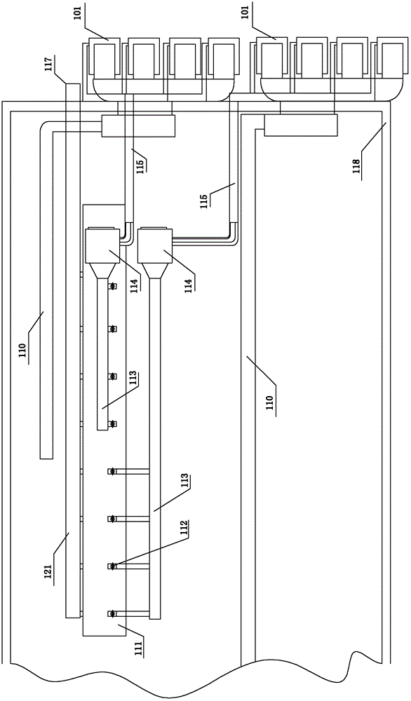
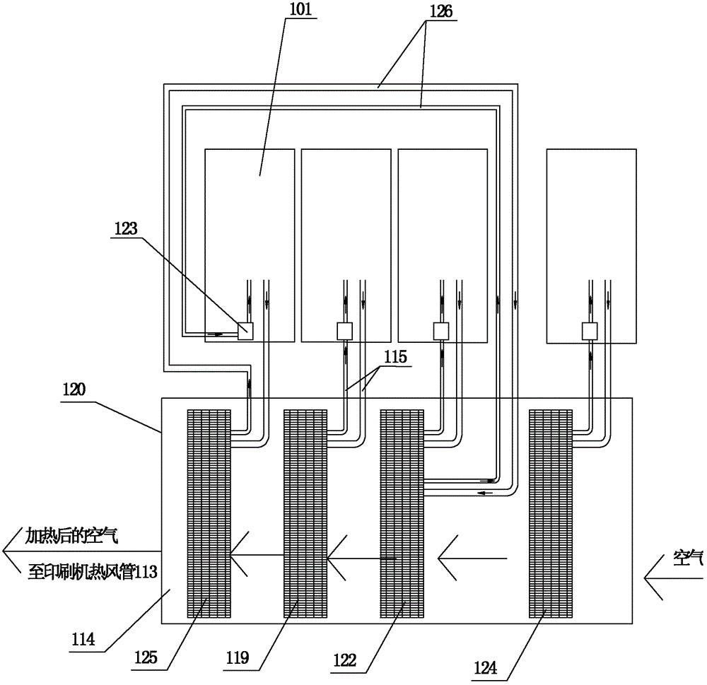
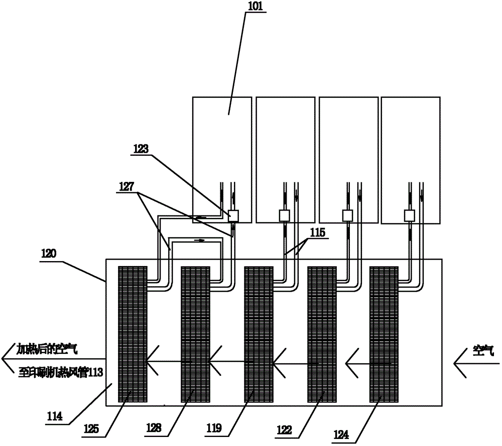
[0027] Situation after adopting technical scheme of the present invention to transform: see figure 1 , 2 , reflecting a specific structure of t...

Embodiment 2

[0032] Example 2: Dry compound machine heating transformation project:

[0033] The original status of the project: one 1050mm dry compound machine, the wind speed of the three air inlets is 2000m 3 About / h, the high temperature zone is required to be 80°C-83°C, the medium temperature zone is 71°C-74°C, and the low temperature zone is 62°C-65°C. Because the exhaust gas contains organic solvents, the air source heat pump cannot be used for circulating air heating, and the air source heat pump is used to heat the air with direct current air, and the air temperature cannot meet the requirements, so the electric heating tube heating method is used. The power of the electric heating tube in the high temperature zone of the dry compound machine is 70KW, the power of the electric heating tube in the medium temperature zone is 55KW, the power of the electric heating tube in the low temperature zone is 50KW, and the total electric heating power is 175KW. When the ambient temperature ...


PUM


Abstract

The invention provides an air source heat pump system for providing direct high temperature air. The air source heat pump system consists of a plurality of air source heat pumps; condensers of the plurality of air source heat pumps are connected in series to form a condenser group for multi-stage heating, air to be heated passes through the condensers of the air source heat pumps in turn, and hot air temperatures of the condensers of the air source heat pumps are improved in turn according to an air inlet sequence; and a condenser fan is arranged at an air outlet of the condenser group for induced draft heat exchange. The air source heat pump system overcomes the technical prejudice that high temperature hot air cannot be acquired in a direct air mode by a heat pump technology, solves the problem that the air source heat pump cannot continuously provide 85DEG C high temperature hot air in the direct air mode, expands the application space and application prospect of the air source heat pump, and has obvious energy saving and emission reducing effects in the field of heating of direct air source heat pumps.

Description

technical field [0001] The invention relates to a device for industrial heating or drying by using an air source heat pump to obtain direct-current high-temperature hot air. Background technique [0002] Circulating wind refers to the wind flow in which all or part of the return air enters the same inlet air. DC wind is a relative concept of circulating wind. Many places in the prior art use 60-80°C high-temperature DC hot air for heating, for example: [0003] 1. In the large-scale industrial production of noodles, most of the pressed noodles are placed on a tunnel-type production line and dried by hot air. The noodles move forward at a speed of several meters per minute, requiring continuous hot air at a temperature of 70 Dry it at about ℃, the higher the air temperature, the more conducive to improving production capacity and quality. The traditional method is to heat the heat transfer oil in a coal-fired boiler, send the heat energy to the heat exchanger in the tunnel...

Claims


Application Information

Patent Timeline
Patent Type & Authority Patents(China)
IPC IPC(8): F26B21/00F25B30/06F24H4/06
Inventor 汤世国汤慧鑫
Owner 湖南省浏阳市择明热工器材有限公司
Features
  • R&D
  • Intellectual Property
  • Life Sciences
  • Materials
  • Tech Scout
  • Unparalleled Data Quality
  • Higher Quality Content
  • 60% Fewer Hallucinations
Learn More