[0026] The embodiments of the present invention are described in detail below. Examples of the embodiments are shown in the accompanying drawings, in which the same or similar reference numerals indicate the same or similar elements or elements with the same or similar functions. The embodiments described below with reference to the drawings are exemplary, and are only used to explain the present invention, but should not be understood as limiting the present invention.
[0027] In the description of the present invention, it should be understood that the terms "center", "longitudinal", "transverse", "upper", "lower", "front", "rear", "left", "right", " The orientation or positional relationship indicated by "vertical", "horizontal", "top", "bottom", "inner", "outer", etc. are based on the orientation or positional relationship shown in the drawings, and are only for the convenience of describing the present invention and simplifying The description does not indicate or imply that the pointed device or element must have a specific orientation, be constructed and operated in a specific orientation, and therefore cannot be understood as a limitation of the present invention. In addition, the terms "first" and "second" are only used for descriptive purposes, and cannot be understood as indicating or implying relative importance.
[0028] In the description of the present invention, it should be noted that the terms "installation", "connected" and "connected" should be understood in a broad sense, unless otherwise clearly specified and limited. For example, they can be fixed or detachable. Connected or integrally connected; it can be a mechanical connection or an electrical connection; it can be directly connected or indirectly connected through an intermediate medium, and it can be the internal communication between two components. For those of ordinary skill in the art, the specific meanings of the above-mentioned terms in the present invention can be understood in specific situations. In addition, in the description of the present invention, unless otherwise specified, "plurality" means two or more.
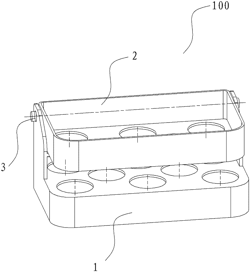
[0029] Reference below Figure 1-Figure 2 Describes an egg rack assembly 100 used in a refrigerator according to an embodiment of the present invention. The egg rack assembly 100 is set in a refrigerator compartment for storing eggs, such as eggs, duck eggs, or egg-like foods.
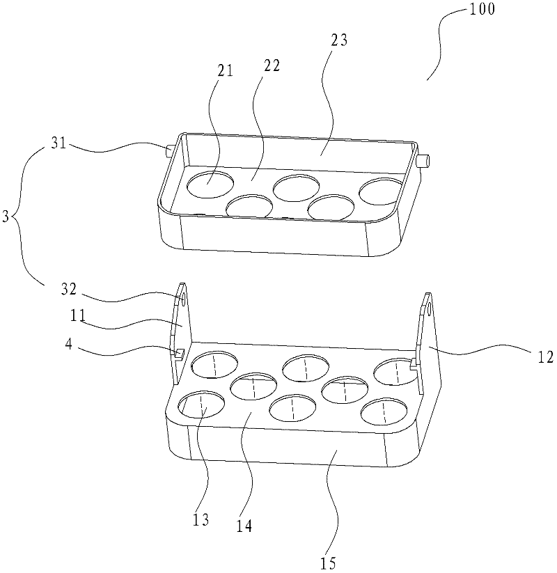
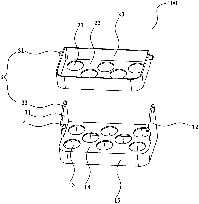
[0030] The egg rack assembly 100 used in the refrigerator according to the embodiment of the present invention includes a first egg rack 1 and a second egg rack 2, wherein the left and right sides of the first egg rack 1 are respectively provided with upwardly extending left side plates 11 and On the right side plate 12, the first egg rack 1 is provided with a plurality of first egg holes 13 for placing eggs. The left and right ends of the second egg rack 2 are respectively pivotably provided on the left side plate 11 and the right side plate 12, and the second egg rack 2 is provided with a plurality of second egg holes 21 for placing eggs. That is, the second egg rack 2 can pivot between the first position and the second position relative to the first egg rack 1, wherein when the second egg rack 2 is in the first position, the first egg rack 1 and the second egg rack 1 Eggs can be stored on the egg rack 2, and when the second egg rack 2 is in the second position, the second egg rack 2 is turned backward by a predetermined angle, and the first egg rack 1 can store eggs at this time. As a result, more eggs can be stored to meet the requirements of different users, and the utility is good. Optionally, the predetermined angle is 90°, so that it is convenient for the user to turn the second egg rack 2 backwards to take the eggs stored on the first egg rack 1 and the operation is simple.
[0031] According to the egg rack assembly 100 used in the refrigerator according to the embodiment of the present invention, more eggs can be stored on the first egg rack 1 and the second egg rack 2, which is convenient and practical. The user can eat the second egg rack 2 first. When the eggs on the second egg rack 2 are taken out, the second egg rack 2 can be turned back relative to the first egg rack 1 and then the eggs on the first egg rack 1 can be used, which not only saves The available storage space in the refrigerator enables the storage space in the refrigerator to be more rationally utilized, and at the same time, the user is convenient to operate when taking eggs and has good practicability.
[0032] In an embodiment of the present invention, the first egg rack 1 includes a first shelf 14 and a first peripheral wall panel 15, wherein the first peripheral wall panel 15 extends downward from the outer peripheral edge of the first shelf 14, where The outer peripheral edge can be understood in a broad sense. For example, the first peripheral wall 15 may extend downward from the outer peripheral surface of the first shelf 14. Advantageously, the upper edge of the first peripheral wall 15 is flat with the upper surface of the first shelf 14. Qi. Optionally, the first peripheral wall panel 15 may extend downward from the outer peripheral edge of the bottom surface of the first shelf 14. A plurality of first egg holes 13 are provided on the first shelf 14. Optionally, the first egg holes 13 are circular holes. Of course, the present invention is not limited to this, and the first egg hole 13 may also be other polygonal holes or square holes, etc., so as to facilitate the storage of eggs.
[0033] In an example of the present invention, the left side plate 11 is formed to extend upward from the left side of the first shelf 14 and the right side plate 12 is formed to extend upward from the right side of the first shelf 11. Optionally, the left side plate 11 and the right side plate 12 are respectively integrally formed with the first egg rack 1, thereby facilitating production and reducing costs.
[0034] In an embodiment of the present invention, the second egg rack 2 includes a second shelf 22 and a second peripheral wall 23, wherein the second peripheral wall 23 extends upward from the outer periphery of the second shelf 22, where the outer periphery may In a broad sense, for example, the second peripheral wall 23 may extend upward from the outer peripheral surface of the second shelf 22. Advantageously, the lower edge of the second peripheral wall 23 is flush with the lower surface of the second shelf 22. Optionally, the second peripheral wall 23 may extend upward from the outer periphery of the top surface of the second shelf 22. A plurality of second egg holes 21 are provided on the second shelf 22. Optionally, the second egg holes 21 are circular holes. Of course, the present invention is not limited to this, and the second egg hole 21 may also be other polygonal holes or square holes, etc., so as to facilitate the storage of eggs.
[0035] In an embodiment of the present invention, the egg rack assembly 100 further includes a pivot assembly 3, and the second egg rack 2 is pivotally provided on the left side plate 11 and the right side plate 12 through the pivot assembly 3.
[0036] In an example of the present invention, such as figure 2 As shown, the pivot assembly 3 includes a pin shaft 31 and a shaft hole 32, wherein the pin shaft 31 is respectively provided on the left and right sides of the second peripheral wall plate 23, and the shaft hole 32 is provided on the left side plate 11 and the right side plate 12, respectively. The pin 31 cooperates with the shaft hole 32 so that the second egg rack 2 is pivotally provided on the left side plate 11 and the right side plate 12.
[0037] Of course, the present invention is not limited to this. In another example of the present invention, the shaft holes 32 can be respectively provided on the left and right sides of the second peripheral wall plate 23, and the pin shafts 31 can be respectively provided on the left side plate 11 and the right side plate. 12, the pin shaft 31 cooperates with the shaft hole 32 so that the second egg rack 2 is pivotally provided on the left side plate 11 and the right side plate 12, not shown in the figure.
[0038] In an embodiment of the present invention, the egg rack assembly 100 further includes a pair of stoppers 4, which are provided on the opposite inner sides of the left side plate 11 and the right side plate 12, such as figure 2 Shown. Thus, by providing a pair of stoppers 4 to stop and support the second egg rack 2, the second egg rack 2 can be stably located in the first position, which is convenient for storing eggs, has good practicability, and reflects the structure of the egg rack assembly 100 Humanized design.
[0039] According to the egg rack assembly 100 used in a refrigerator according to the embodiment of the present invention, more eggs can be stored on the egg rack assembly 100 to meet the needs of different users, and when the eggs on the second egg rack 2 are taken out The second egg rack 2 can be flipped back conveniently and the eggs on the first egg rack 1 can be easily used. The operation is convenient and simple, so that the storage space in the refrigerator can be better utilized, and the practicality is good. The user brings convenience.
[0040] A refrigerator according to an embodiment of the second aspect of the present invention includes a box body, a door body, and the egg rack assembly 100 used in the refrigerator described in the embodiment of the first aspect of the present invention, wherein the front side of the box body is open, and the door body can be It is rotatably arranged on the box body for opening and closing the box body. A shelf tray is arranged on the door body, and the egg rack assembly 100 is arranged in the shelf tray.
[0041] Other components and operations of the refrigerator, such as an evaporator, a compressor, etc., and operations are known to those of ordinary skill in the art, and will not be described in detail here.
[0042] In the description of this specification, descriptions with reference to the terms "one embodiment", "some embodiments", "exemplary embodiments", "examples", "specific examples", or "some examples" etc. mean to incorporate the implementation The specific features, structures, materials or characteristics described by the examples or examples are included in at least one embodiment or example of the present invention. In this specification, the schematic representations of the above terms do not necessarily refer to the same embodiment or example. Moreover, the described specific features, structures, materials or characteristics may be combined in any one or more embodiments or examples in a suitable manner.
[0043] Although the embodiments of the present invention have been shown and described, those of ordinary skill in the art can understand that various changes, modifications, substitutions, and modifications can be made to these embodiments without departing from the principle and purpose of the present invention. The scope of the present invention is defined by the claims and their equivalents.